Safety
Information
Product
information
Mechanical
Installation
Electrical
installation
Getting
started
Basic
parameters
Running the
motor
Optimization
SMARTCARD
operation
Onboard
PLC
Advanced
parameters
Technical
data
Diagnostics
UL
information
48 Mentor MP User Guide
www.controltechniques.com Issue: 3
ground conductors at both ends of the cable must be bonded
together by a power ground cable (equipotential bonding cable) with
cross-sectional area of at least 10mm
2
, or 10 times the area of the
signal cable shield, or to suit the electrical safety requirements of the
plant. This ensures that fault or surge current passes mainly through
the ground cable and not in the signal cable shield. If the building or
plant has a well-designed common bonded network this precaution
is not necessary.
3. Additional over-voltage suppression - for the analog and digital
inputs and outputs, a zener diode network or a commercially
available surge suppressor may be connected in parallel with the
input circuit as shown in Figure 4-14 and Figure 4-15.
Figure 4-14 Surge suppression for digital and unipolar inputs and
outputs
Figure 4-15 Surge suppression for analog and bipolar inputs and
outputs
Surge suppression devices are available as rail-mounting modules, e.g.
from Phoenix Contact:
Unipolar TT-UKK5-D/24 DC
Bipolar TT-UKK5-D/24 AC
These devices are not suitable for encoder signals or fast digital data
networks because the capacitance of the diodes adversely affects the
signal. Most encoders have galvanic isolation of the signal circuit from
the motor frame, in which case no precautions are required. For data
networks, follow the specific recommendations for the particular
network.
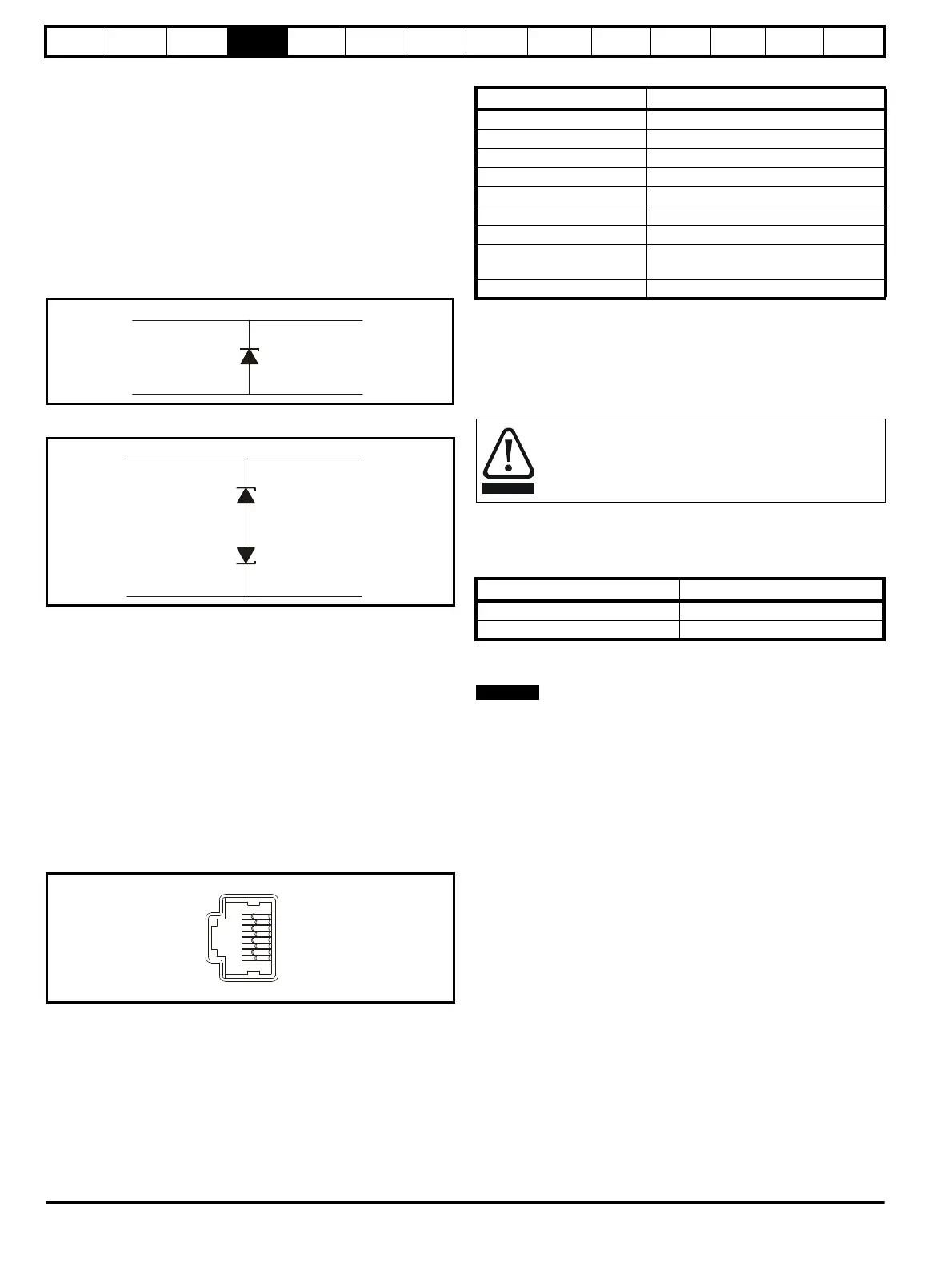
4.10 Serial communications connections
The Mentor MP has a serial communications port (serial port) as
standard supporting two wire EIA(RS)-485 communications. See Table
4-22 for the connection details for the RJ45 connector.
Figure 4-16 Serial communications port
Table 4-22 RJ45 connections
The communications port applies a two-unit load to the communications
network. Connectors 2, 3, 7 and shield must always be made to the
serial communications port. Shielded cable must be used at all times.
4.10.1 Isolation of the serial communications port
The serial PC communications port is double insulated and meets the
requirements for SELV in EN 50178.
An isolated serial communications lead has been designed to connect
the drive to IT equipment (such as lap-top computers), and is available
from the supplier of the drive. See Table 4-23 for details.
Table 4-23 Isolated serial comms lead details
The “isolated serial communications” lead has reinforced insulation as
defined in IEC 60950 for altitudes up to 3,000m.
N
When using the CT EIA232 Comms cable the available baud rate is
limited to 19.2k baud.
4.10.2 Multi-drop network
The drive can be used on a 2 wire EIA485 multi-drop network using the
drive's serial communications port when the following guidelines are
adhered to.
Connections
The network should be a daisy chain arrangement and not a star,
although short stubs to the drive are allowed.
The minimum connections are pins 2 (RX TX), 3 (isolated 0V), 7 (RX\
TX\) and the shield.
Pin 4 (+24V) on each drive can be connected together but there is no
power sharing mechanism between drives and therefore the maximum
power available is the same as a single drive. (If pin 4 is not linked to the
other drives on the network and has an individual load then the
maximum power can be taken from pin 4 of each drive.)
Termination resistors
If a drive is on the end of the network chain then pins 1 and 8 should be
linked together. This will connect an internal 120Ω termination resistor
between RXTX and RX\TX\. (If the end unit is not a drive or the user
wishes to use their own termination resistor, a 120Ω termination resistor
should be connected between RXTX and RX\TX\ at the end unit.)
If the host is connected to a single drive then termination resistors
should not be used unless the baud rate is high.
CT Comms cable
The CT Comms cable can be used on a multi-drop network but should
only be used occasionally for diagnostic and set up purposes. The
network must also be made up entirely of Mentor MPs.
Signal from plant Signal to drive
0V 0V
30V zener diode
e.g. BZW50-15
Signal from plant Signal to drive
0V 0V
2 x 15V zener diode
e.g. 2xBZW50-15
Pin Function
1 120Ω Termination resistor
2RX TX
3 0V isolated
4 +24V (100 mA)
5 0V isolated
6 TX enable
7RX\ TX\
8
RX\ TX\(if termination resistors are
required, jumper (link) to pin 1)
Shell 0V isolated
In order to meet the requirements for SELV in IEC 60950 (IT
equipment) it is necessary for the control computer to be
grounded. Alternatively, when a lap-top or similar device is
used which has no provision for grounding, an isolation
device must be incorporated in the communications lead.
Part number Description
4500-0087 CT EIA232 Comms cable
4500-0096 CT USB Comms cable