Safety
Information
Product
information
Mechanical
Installation
Electrical
installation
Getting
started
Basic
parameters
Running the
motor
Optimization
SMARTCARD
operation
Onboard
PLC
Advanced
parameters
Technical
data
Diagnostics
UL
information
Mentor MP User Guide 27
Issue: 3 www.controltechniques.com
The enclosure is to be made from painted 2mm (0.079in) sheet steel
having a heat transmission coefficient of 5.5 W/m
2
/
o
C. Only the top,
front, and two sides of the enclosure are free to dissipate heat.
The value of 5.5 W/m
2
/ºC can generally be used with a sheet steel
enclosure (exact values can be obtained by the supplier of the material).
If in any doubt, allow for a greater margin in the temperature rise.
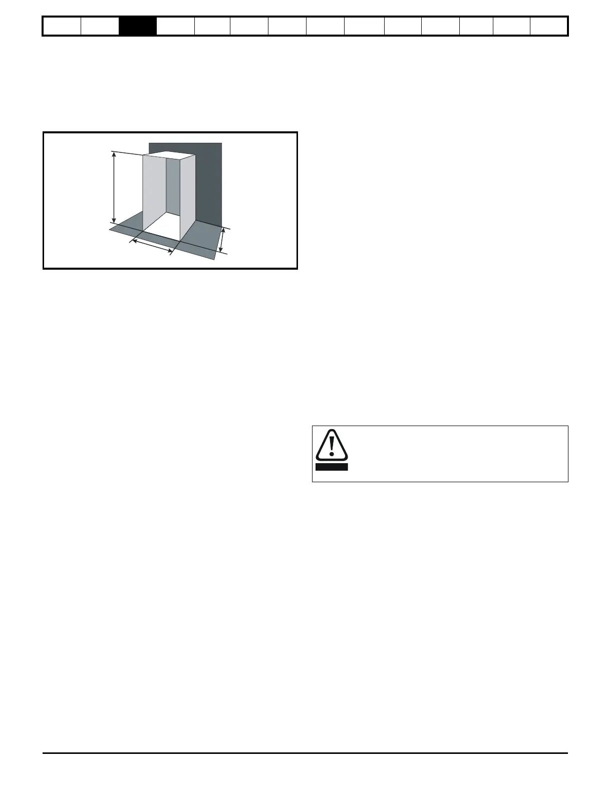
Figure 3-18 Enclosure having front, sides and top panels free to
dissipate heat
Insert the following values:
T
int
40°C
T
ext
30°C
k 5.5
P 272W
The minimum required heat conducting area is then:
= 4.945 m
2
(53.90 ft
2
) (1 m
2
= 10.9 ft
2
)
Estimate two of the enclosure dimensions - the height (H) and depth (D),
for instance. Calculate the width (W) from:
Inserting H = 2m and D = 0.6m, obtain the minimum width:
=0.979 m (38.5 in)
If the enclosure is too large for the space available, it can be made
smaller only by attending to one or all of the following:
• Reducing the ambient temperature outside the enclosure, and/or
applying forced-air cooling to the outside of the enclosure
• Reducing the number of drives in the enclosure
• Removing other heat-generating equipment
Calculating the air-flow in a ventilated enclosure
The dimensions of the enclosure are required only for accommodating
the equipment. The equipment is cooled by the forced air flow.
Calculate the minimum required volume of ventilating air from:
Where:
V Air-flow in m
3
per hour (1 m
3
/hr = 0.59 ft
3
/min)
T
ext
Maximum expected temperature in
°C outside the
enclosure
T
int
Maximum permissible temperature in °C inside the
enclosure
P Power in Watts dissipated by all heat sources in the
enclosure
k Ratio of
Where:
P
0
is the air pressure at sea level
P
I
is the air pressure at the installation
Typically use a factor of 1.2 to 1.3, to allow also for pressure-drops in
dirty air-filters.
Example
To calculate the size of an enclosure for the following:
• Three MP45A4 models operating under full load conditions
• Maximum ambient temperature inside the enclosure: 40°C
• Maximum ambient temperature outside the enclosure: 30°C
Dissipation of each drive: 168W
Dissipation from other heat generating equipment. 15 W
Total dissipation: 3 x (168 + 15) = 549W
Insert the following values:
T
int
40°C
T
ext
30°C
k 1.3
P 549W
Then:
= 214.1 m
3
/hr (126.3 ft
3
/min) (1 m
3
/ hr = 0.59 ft
3
/min)
3.7 Heatsink fan operation
Mentor MP drive rated 75A and above are ventilated by internally
supplied fans.
Ensure the minimum clearances around the drive are maintained to
allow the air to flow freely.
The drive controls the fan operation based on the temperature of the
heatsink and the drives thermal model system.
3.8 IP rating (Ingress Protection)
An explanation of IP rating is provided in section 12.1.13 IP rating on
page 150.
A
e
272W
5.5 40 30–()
---------------------------------
=
W
A
e
2HD–
HD+
--------------------------
=
W
4.945 2 2× 0.6×()–
20.6+
-----------------------------------------------------
=
V
3kP
T
int
T
ext
–
---------------------------
=
IP rating
It is the installer’s responsibility to ensure that any enclosure
which allows access to drives from frame sizes 2A to 2D
while the product is energized, provides protection against
contact and ingress to the requirements of IP20.
V
31.3× 549×
40 30–
----------------------------------
=