Safety
Information
Product
information
Mechanical
Installation
Electrical
installation
Getting
started
Basic
parameters
Running the
motor
Optimization
SMARTCARD
operation
Onboard
PLC
Advanced
parameters
Technical
data
Diagnostics
UL
information
58 Mentor MP User Guide
www.controltechniques.com Issue: 3
5.3 Menu 0 (sub block)
Menu 0 can be accessed by 2 methods:
1. Pr 11.44 (SE14, 0.35) = 0. Sub block mode.
2. Pr 11.44 (SE14, 0.35) <>0. Linear mode.
Menu 23 contains the parameters to allow menu 0 to be customized in
sub block mode. The first sub block is a user defined area (USEr) which
is configured by the parameters in menu 22. As default there are no
parameters configured to the user sub block and so it is empty. The next
7 sub blocks are pre-defined. Access to the pre-defined blocks is
enabled or disabled by Pr 23.03 to Pr 23.09.
Movement between sub blocks is achieved with the left and right keys.
Pr 23.01 contains all the sub block headers.
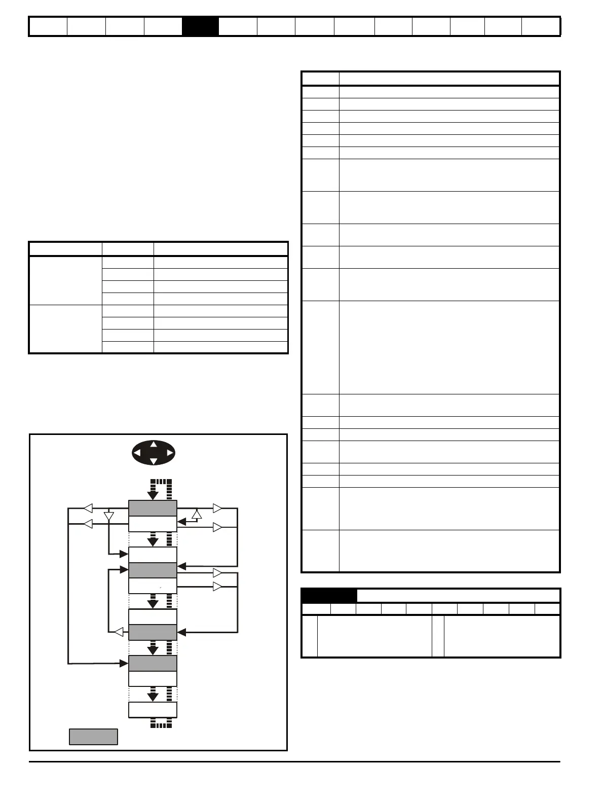
Table 5-1 and Figure 5-5 show the result of the direction keys when
Pr 11.44 (SE14, 0.35) is set to L1 (0). When Pr 11.44 (SE14, 0.35)is not
0 the left and right keys will allow access to the advance parameter set
and menu 0 will become a linear menu.
Table 5-1 Keypad navigation
When moving to the user block header, the user block header is only
displayed if there are some valid parameters in the block. When moving
between pre-defined header blocks the pre-defined header block is only
displayed if the pre-defined block is enabled.
When moving between parameters within a block, only valid parameters
are displayed.
Figure 5-5 Sub block navigation
Coding
The coding defines the attributes of the parameter as follows.
Defines the sub block headers. Can be used by the MP-Keypad to
display the same strings as the SM-Keypad.
Starting location Action Finishing location
Header
Right Next header
Left Previous header
Up First parameter in header block
Down Last parameter in header block
Parameter
Right Next header
Left Previous header
Up Next parameter in header block
Down Previous parameter in header block
SEt UP
diAGnoS
inPut
Headers
triPS
SE00
SE13
di01
di14
in01
in10
Coding Attribute
{X.XX} Copied Mneu 0 or advanced parameter
Bit 1 bit parameter: ‘On’ or ‘OFF’ on the display
Bi Bipolar parameter
Uni Unipolar parameter
Txt Text: the parameter uses text strings instead of numbers.
SP Spare: not used
FI
Filtered: some parameters which can have rapidly changing
values are filtered when displayed on the drive keypad for
easy viewing.
DE
Destination pointer parameter: This parameter can be used
to set up the location (i.e. menu/parameter number) where
the destination data is to be routed.
VM
Variable maximum: the maximum of this parameter can
vary.
DP
Decimal place: indicates the number of decimal places used
by this parameter.
ND
No default: when defaults are loaded (except when the drive
is manufactured or on EEPROM failure) this parameter is
not modified.
RA
Rating dependant: this parameter is likely to have different
values and ranges with drives of different voltage and
current ratings. Parameters with this attribute will not be
transferred to the destination drive by a SMARTCARD when
the rating of the destination drive is different from the source
drive if the drive voltage ratings are different or the file is a
parameter file. However, the value will be transferred if only
the current rating is different and the file is a differences
from default type file.
NC
Not copied: not transferred to or from SMARTCARD during
copying.
NV Not visible: not visible on the keypad.
PT Protected: cannot be used as a destination.
US
User save: saved in drive EEPROM when the user initiates
a parameter save.
RW Read/write: can be written by the user.
RO Read only: can only be read by the user
BU
Bit default one/unsigned: Bit parameters with this flag set to
one have a default of one (all other bit parameters have a
default of zero. Non-bit parameters are unipolar if this flag is
one.
PS
Power-down save: parameter automatically saved in drive
EEPROM when the under volts (UV) trip occurs. Power-
down save parameters are also saved in the drive when the
user initiates a parameter save.
23.01 Sub block headers
RO Txt NC PT BU
Ú
USEr (0), SEt UP (1),
diAGnoS (2), triPS (3), SP
LOOP (4), Fb SP (5), SintEr
(6), inPut (7)
Ö
USEr (0)