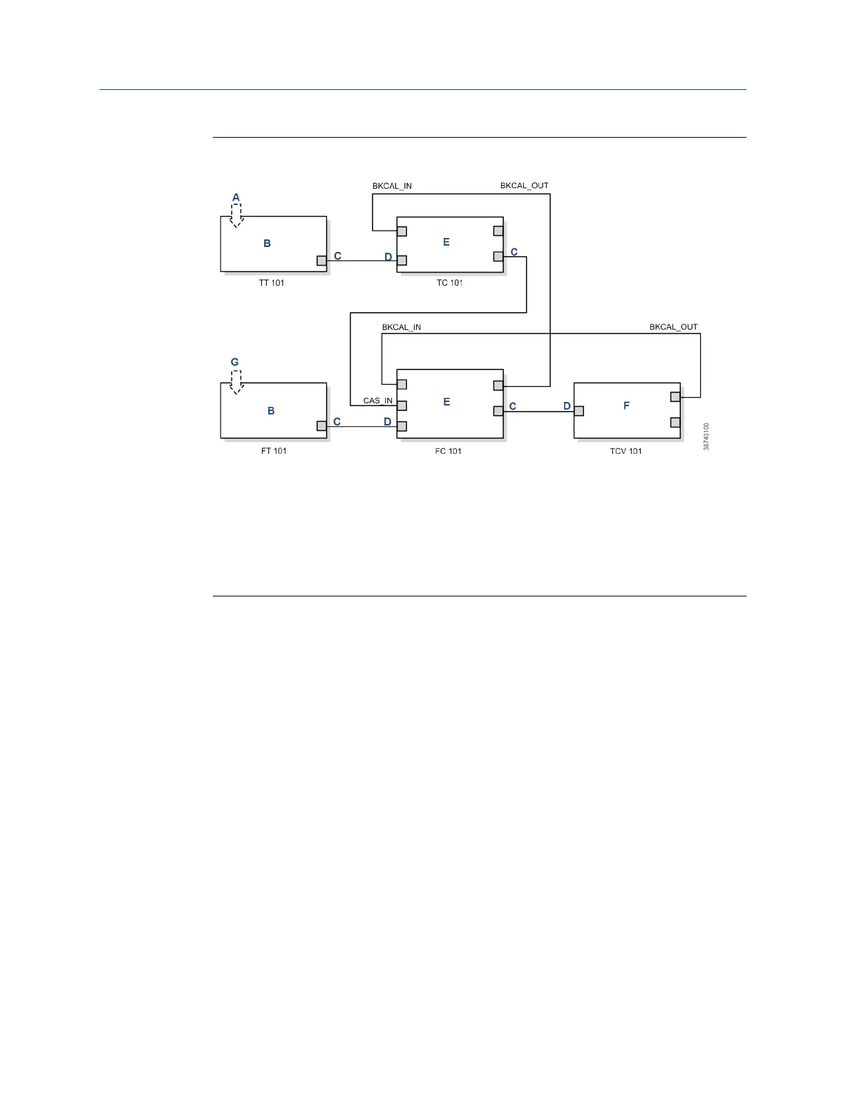
Figure 8-22: PID Function Block Diagram for Cascade Control Example
A. Outlet temperature input
B. AI function block
C. Out
D. In
E. PID function block
F. AO module block
G. Steam flow input
Cascade control with override
You can use the proportional/integral/derivative (PID) function block with other
function blocks for complex control strategies.
Figure 8-23 illustrates the function block diagram for cascade control with
override.
When configured for cascade control with override, if one of the PID function
blocks connected to the selector input is deselected, that PID block filters the
integral value to the selected value (the value at its BKCAL_IN). The selected PID
block behaves normally, and the deselected controller never winds up. At steady
state, the deselected PID block offsets its OUT value from the selected value by
the proportional term. When the selected block becomes output-limited, it
prevents the integral term from winding further into the limited region.
When the cascade between the slave PID block and the control selector block is
open, the open cascade status is passed to the control selector block and through
to the PID block supplying input to it. The control selector block and the upstream
(master) PID blocks have an actual mode of IMan.
If the instrument connected to the AI block fails, you can place the AI block in
Manual mode and set the output to some nominal value for use in the Integrator
function block. In this case, IN at the slave PID block is constant and prevents the
integral term from increasing or decreasing.
Manual
FOUNDATION
™
Fieldbus
00809-0500-4880 December 2022
Rosemount OCX8800A 189