4. Remove the cover from the electronics housing to expose the electronics
housing and terminal blocks, Figure 10-2.
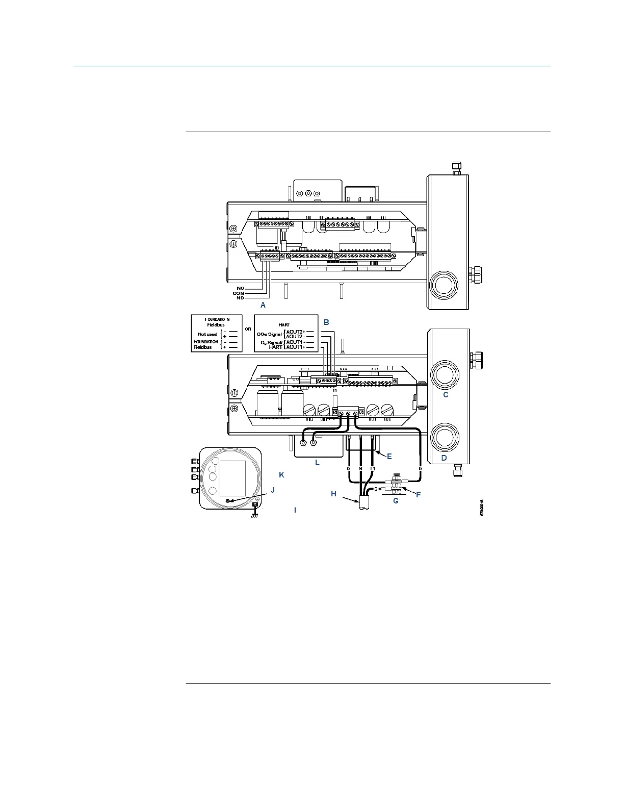
Figure 10-2: Electronics Housing Terminal Blocks
A. Alarm output relay terminal block
B. Signal output terminal block
C. Signal port ¾ national pipe thread (NPT)
D. Power port ¾ NPT
E. Terminal block
F. External tooth lockwasher
G. Ground stud
H. Customer wiring
I. Earth ground typical for electronics and sensor housing
J. Ground stud
K. Top view (½ size)
5. Disconnect and remove the power leads from the AC power input terminal
block and remove the ground lead from the ground stud.
Manual Maintenance and service
00809-0500-4880 December 2022
Rosemount OCX8800A 239