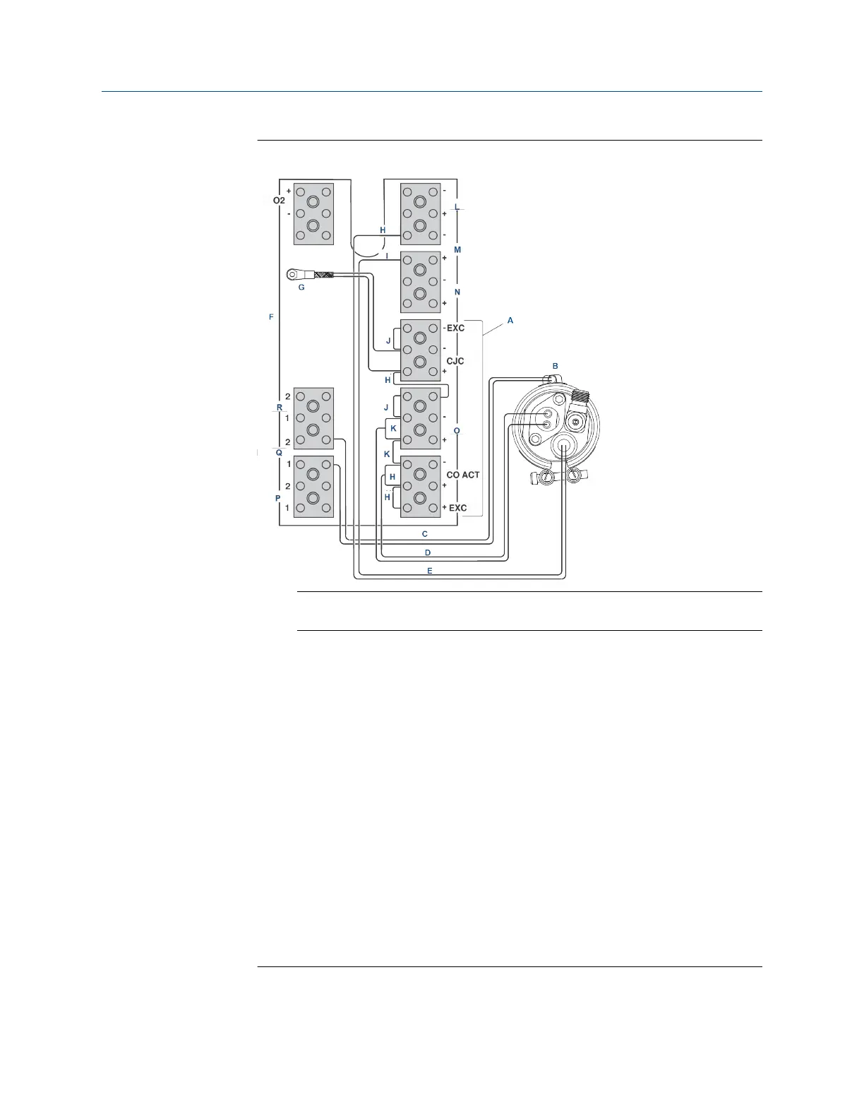
Figure 10-9: COe Sensor, Thermocouple, and Heater Connections
A.
Note
All wires at these terminals are in the CJC current loop.
B. COe sensor assembly
C. COe heater wires
D. COe sensor wires
E. COe thermocouple wires
F. Sensor housing terminals
G. CJC sensor
H. Red
I. Yellow
J. Blue
K. White
L. Thermocouple O
2
M. Thermocouple CO
N. Thermocouple sample block
O. CO reference
P. Heater sample block
Q. Heater CO
R. Heater 02
2. Remove insulator (A, Figure 10-10).
Maintenance and service Manual
December 2022 00809-0500-4880
254 Emerson.com/Rosemount