EasyManua.ls Logo

Emotron M20 - Three-Phase Connection Example; Selection of Current Transformer; For Motors Under 100 A

Emotron M20
56 pages
Print Icon
To Next Page IconTo Next Page
To Previous Page IconTo Previous Page
Loading...
CG Drives & Automation 01-5958-01r0
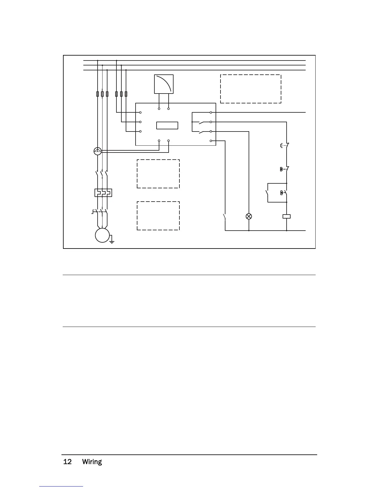
Fig. 1 Connection example
Please use the enclosed plastic (rubber) insert (if ordered, optional) to cover the
monitor terminals.
NOTE: If the START/STOP is connected as per Fig. 1, it is recommended that
terminals 6 and 7 be bypassed during programming. After the programming
is completed the bypass must be taken out. Make sure that the monitor
voltage range e.g. 3x380-500 VAC matches the connected motor/line
voltage, e.g. 3x 400 V.
M20
A+ A-
R1
R2
C
L1
L3
L2
S2S1
DIG
{
L1
L2
L3
K1
U
V
W
M
K1
K1
3
4
9
11
13
1
2
6
7
8
5
Stop
Start
N (alt. 48 VDC+)
Max. 240 VAC (alt. 0 VDC-)
NOTE: in power down,
both relays are alwas
N.O.
Please see CTM
information
on Page 11.
NOTE: Monitor
voltage see
Note below.

Related product manuals