EasyManua.ls Logo

Emotron M20 - User Manual

Emotron M20
56 pages
Print Icon
To Next Page IconTo Next Page
Loading...
Emotron M20
Shaft power monitor
Instruction manual
English

Questions and Answers

  • E
    Eric JacobsAug 16, 2025
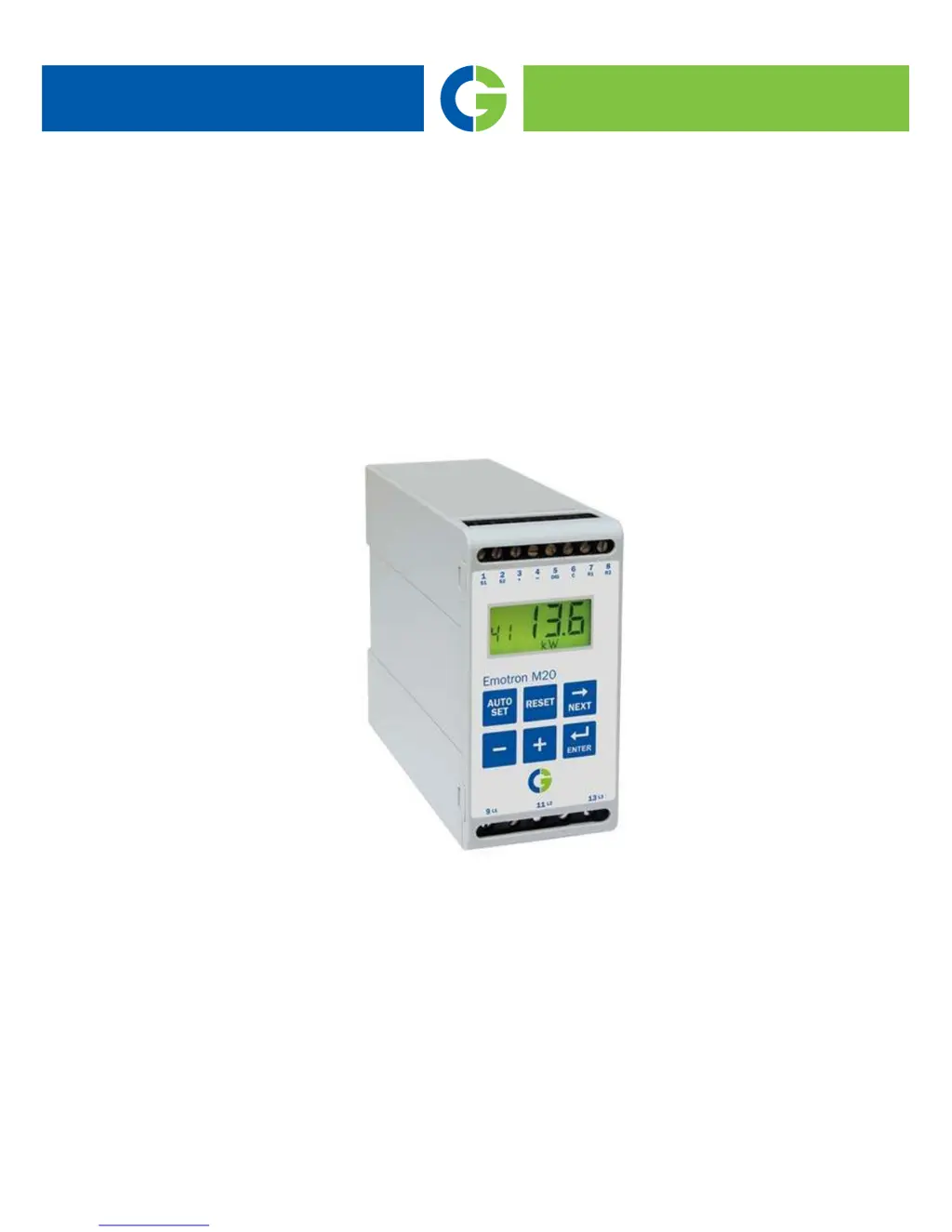
    What to do if window 01 shows an improper power value on my Emotron Protection Device?
    • M
      Martin HallAug 16, 2025
      If window 01 on your Emotron Protection Device shows an improper power value while the motor is running, verify that the motor isn't oversized for its application and check the power transmission and gear ratio. Also, ensure there's a load on the motor during normal operation and that the change in motor load is greater than about 3%. Lastly, confirm that the current transformer is connected in phase L1.
  • J
    Jeffrey AndersonAug 19, 2025
    How to troubleshoot window 01 always showing zero load on my Emotron M20?
    • A
      Alexis BurnsAug 19, 2025
      If window 01 of your Emotron Protection Device always shows zero load, even when the motor is running, check the connection of the current transformer(s). Also, make sure that the value of the rated motor power in window 41 matches the rated motor power on the motor plate. Finally, verify that window 03 displays a phase current value that aligns with the rated motor current.
  • M
    Mary StewartAug 22, 2025
    Why does my Emotron M20 Protection Device always give an alarm?
    • D
      Dylan MillsAug 22, 2025
      If your Emotron Protection Device always gives an alarm, check the alarm levels in windows 11 to 14 and readjust them or perform an Auto set if they are incorrect. Also, check if the monitor is programmed for “latched alarm” (window 61=on). If it is, reset the monitor by pressing the reset key.
  • P
    Patricia YoungAug 25, 2025
    What causes an improper phase current value in window 03 of my Emotron M20?
    • B
      bradleywatsonAug 25, 2025
      If window 03 on your Emotron Protection Device shows an improper value for the phase current, check that the current transformer has been selected as per Tables 1 and 2. Also, check that the number of windings is as per Tables 1 and 2. Finally, make sure that the value of the motor current in window 42 is the same as the value of the motor current on the motor plate.
  • K
    kenneth75Aug 27, 2025
    Why doesn't my Emotron M20 ever give an alarm?
    • S
      Susan HodgesAug 27, 2025
      If your Emotron Protection Device monitor never gives an alarm, check that window 01 shows a value greater than zero. Also, check the alarm levels in windows 11 to 14; if they are incorrect, readjust the levels or perform an Auto set.
  • K
    Kyle CruzAug 30, 2025
    What does it mean when window 03 on my Emotron M20 shows “oor”?
    • S
      Sandra GomezAug 30, 2025
      If window 03 on your Emotron Protection Device shows “oor” (“Out Of Range” alarm), it means the measured motor current is higher than 125% of the rated motor current programmed in window 42.
  • S
    Stephen PetersSep 2, 2025
    What does it mean when window 01 on my Emotron M20 displays “oor”?
    • J
      James GallowaySep 2, 2025
      If window 01 on your Emotron Protection Device shows “oor” (“Out Of Range” alarm), the measured shaft power is higher than 125% of the rated motor power programmed in window 41.
  • A
    Adam HubbardSep 5, 2025
    What should I do if window 00 shows “LU” or “OU” on my Emotron M20 Protection Device?
    • L
      Lisa GonzalezSep 5, 2025
      If window 00 on your Emotron Protection Device shows “LU” or “OU” (Under- or over- voltage alarm), switch off the supply. Check that the supply voltage agrees with the voltage range on the monitor type plate.
  • E
    Eric SalazarSep 7, 2025
    What to do if the alarm relays are not switching on my Emotron Protection Device?
    • A
      Amanda HernandezSep 7, 2025
      If the alarm relays on your Emotron Protection Device are not switching, check that the wire links between terminals 6 and 7 are removed as per “Wiring.”
  • I
    Ian TaylorSep 10, 2025
    Why isn't over and undervoltage detected on my Emotron M20 Protection Device?
    • V
      Victoria BaldwinSep 10, 2025
      Over and undervoltage detection with your Emotron Protection Device only occurs at monitor power up, not during continuous operation. Relays will not trip; indication will only be in the display.

Summary

Inside the Box

Safety

Description

Getting Started

Please Note

Important notes before proceeding with setup and connection.

Connection and Setup Before First Start

Steps for connecting the unit and initial setup before powering on.

First Start Procedure

Guide on how to start the motor/machine for the first time.

Manual Alarm Level Setting (Alternative A)

Setting maximum and minimum alarm levels manually.

Manual Alarm Level Setting (Alternatives B & C)

Setting alarm levels based on maximum/minimum loads and approximate calculations.

Wiring

Three-Phase Connection Example

Wiring diagram for three-phase motor connections.

Single-Phase Connection Example

Wiring diagram for single-phase motor connections.

Digital Input Wiring Example

Example of wiring digital inputs to the unit.

Selection of Current Transformer

For Motors Under 100 A

Guide to selecting the correct current transformer for motors below 100 A.

For Motors Over 100 A

Guide to selecting current transformers for motors above 100 A.

Operation

Operational Overview

General overview of the unit's operation and display elements.

Window Menu Navigation

Explanation of the different windows and their functions.

Changing Parameter Values

Step-by-step instructions on modifying parameter values in the unit.

Programming

Setting Measurement Units (kW;HP)

How to select the unit of measurement for power and current.

Setting Rated Motor Power and Current

Configuring the motor's rated power and current values.

Setting Number of Phases

Configuring the number of phases for the motor connection.

Configuring Monitor Function

Setting monitor functions, alarm levels, and start delay parameters.

Setting the Start Delay

Defining the delay period for motor startup to avoid false alarms.

Setting Alarm Levels via Auto Set

Automatically setting alarm levels based on measured motor load.

Setting Response Delay

Configuring delay times before alarm relays are activated.

Advanced Features

Manual Alarm and Margin Settings

Manually configuring alarm levels, margins, hysteresis, and digital input.

Relay Output, Block Timer, and Analogue Output

Configuring relay outputs, block timer, and analogue output signals.

Analogue Output Range and Parameter Locking

Setting analogue output range and locking parameters to prevent changes.

Factory Defaults and Alarm Messages

Resetting to factory defaults and viewing alarm messages.

Special Relay Functions

Configuring special functions like separate relays and reverse operation.

Troubleshooting

Technical Data

Parameter List

Service Information

Emotron M20 Specifications

General IconGeneral
CommunicationModbus RTU
Protection classIP20
MountingDIN rail
TypeMotor protection
Power consumption5 W
Analogue output4-20 mA or 0-20 mA
Rated voltage690 V AC

Related product manuals