CG Drives & Automation 01-5958-01r0
Setting main alarm latch (window 61)
The main alarm latch keeps the main alarm output active, even if the alarm
condition has been removed. A latched alarm output can be reset by:
•The reset key
• External reset via digital input (see window 81).
• Switching off the power to the monitor (see also Wiring).
Default = Off.
Setting alarm at no motor current (window 62)
The alarm at no motor current gives an alarm if the motor current goes down to
zero (62 = on). Default = Off (No alarm at no motor current).
Setting relay output (window 63 and 64 alt. 65)
The relay outputs R1 and R2 can be set to NO or NC contacts.
If separate output relays are required for overload (max., relay R1) and
underload (min., relay R2), see Special functions in chapter 9 and chapter 12.
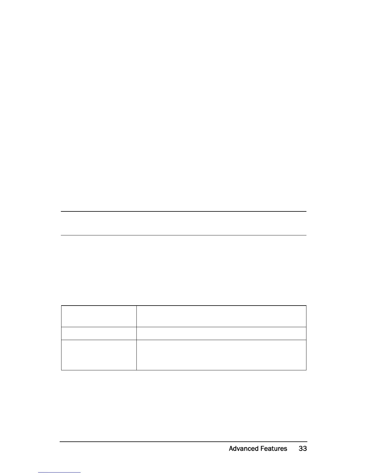
Setting digital input (window 81)
The digital input can be set for:
NOTE: If the power to the load monitor is switched off, the relay contacts
are always in position NO.
RES: External RESET
(Default)
To reset an alarm.
AU: External Auto set To perform an Auto set with an external signal.
bLo: Block Pre-Alarm
To block the Pre-Alarm function and start the Block
timer. If the input is high a Pre-Alarm is blocked, i.e. it is
neglected. See also window 82.