EDM01-36v10 DAG_9.2X2_Card_User_Guide - Installation
©2010 - 2012 Endace Technology Ltd. Confidential - Version 10 - May 2012 11
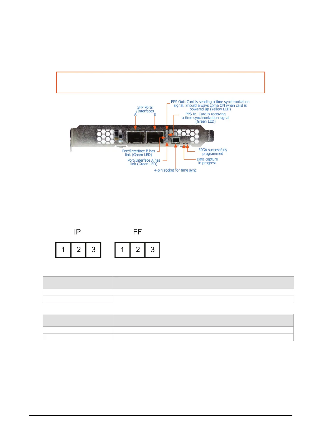
Ports and Status LEDs
The DAG 9.2X2 card has two industry standard port connectors for network connections.
In addition there is a 4-pin socket located beside the port connectors for connection to an external time
synchronization source.
Warning:
Connect only a PPS input to the 4 pin time synchronization socket.
Connecting anything else to this socket may damage the DAG card.
Boot jumper settings
The DAG 9.2X2 has two sets of jumpers mounted on the DAG card which control the card's boot
behavior:
• IP (Inhibit Program)
• FF (Force Factory)
Jumper set between Definition
Used in development. Do not use.
2 & 3 or jumper not fitted
Normal operation of the DAG card.
Jumper set between Definition
Loads the factory image into the FPGA at power on.
2 & 3 (or jumper not fitted)
Loads the user defined image into the FPGA at power on.