EDM01-36v10 DAG_9.2X2_Card_User_Guide - Data formats
66 ©2010 - 2012 Endace Technology Ltd. Confidential - Version 10 - May 2012
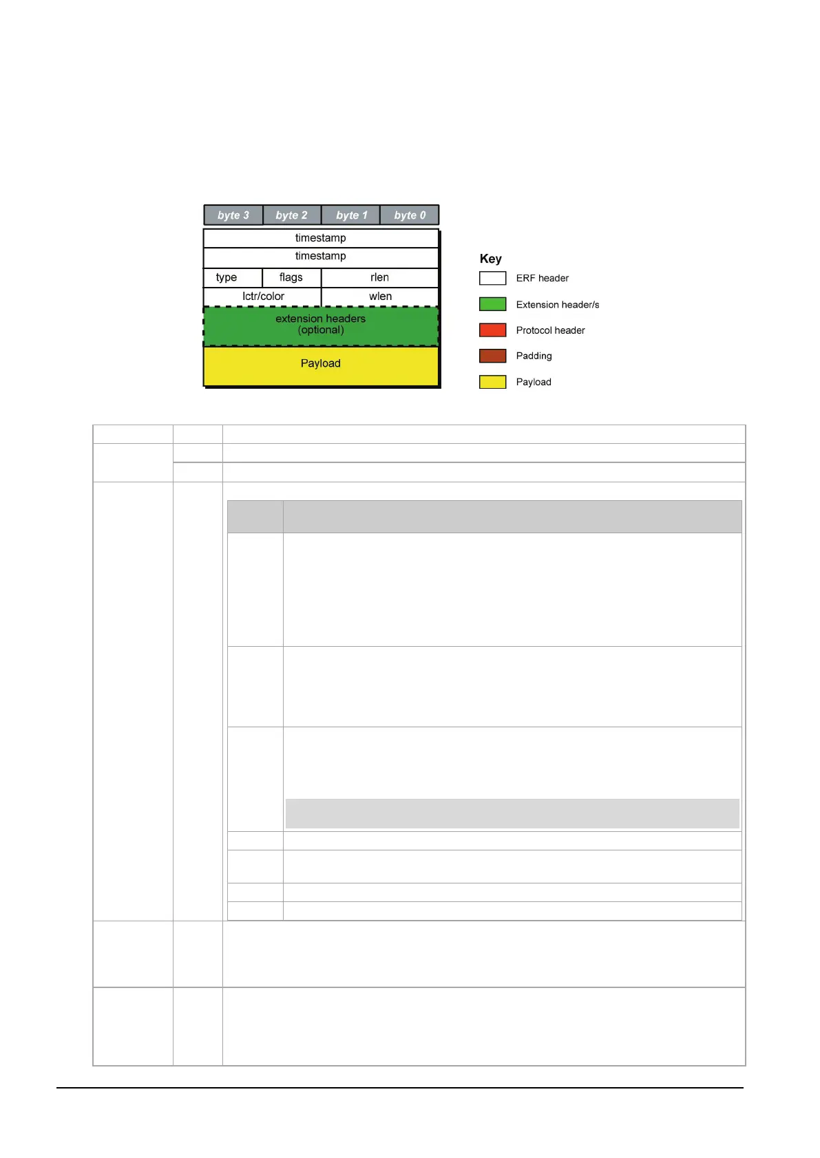
Generic ERF header
All ERF records share some common fields. Timestamps are in little-endian (Pentium
®
native) byte order.
All other fields are in big-endian (network) byte order. All payload data is captured as a byte stream in
network order, no byte or re-ordering is applied.
The generic ERF header is shown below:
The fields are described below:
The time of arrival of the cell, an ERF 64-bit timestamp.
Extension header present.
ERF type. See table below:
This byte is divided into several fields as follows:
Bits Description
Binary enumeration of capture interface:
11 Interface 3 or D 10 Interface
2 or C
01 Interface 1 or B 00 Interface
0 or A
Cards with more than four interfaces typically use Multichannel ERF types (type 5
to 9, 12 and 17) which provide a separate larger interface field.
Varying length record (vlen). When set, packets shorter than the snap length are
not padded and rlen resembles wlen.
When clear, longer packets are snapped off at snap length and shorter packets
are padded up to the snap length. rlen resembles snap length. Setting novarlen
and slen greater than 256 bytes is wasteful of bandwidth
Truncated record - insufficient buffer space.
• wlen is still correct for the packet on the wire.
• rlen is still correct for the resulting record. But, rlen is shorter than expected
from snap length or wlen values.
Truncation is depreciated and this bit is unlikely to be set in an ERF record.
RX error. An error in the received data. Present on the wire
DS error. An internal error generated inside the card annotator. Not present on
the wire.
Record length in bytes. Total length of the record transferred over the PCIe Gen 2.0 bus to
storage.
The timestamp of the next ERF record starts exactly rlen bytes after the start of the
timestamp of the current ERF record.
Depending upon the ERF type this 16 bit field is either a loss counter or color field. The
loss
counter
records the number of packets lost between the DAG card and the stream buffer due
to overloading on the PCIe Gen 2.0 bus. The loss is recorded between the current record and
the previous record captured on the same stream/interface. The
color field
is explained under
the appropriate ERF type details.