EDM01-36v10 DAG_9.2X2_Card_User_Guide - Synchronizing clock time
62 ©2010 - 2012 Endace Technology Ltd. Confidential - Version 10 - May 2012
Connector
Overview
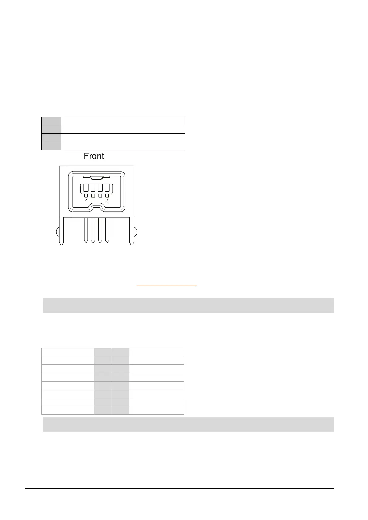
DAG cards have a 4-pin connector for time synchronization. The connector has one bi-directional RS422
differential circuit, A. The Pulse Per Second (PPS) signal is carried on circuit A.
Pin assignments
The 4-pin connector pin assignments and plugs and sockets are shown below:
Normally, you connect the GPS input to the PPS (A) channel input (pins 3 and 4).
The DAG card can also output a synchronization pulse for use when synchronizing two DAG cards, (i.e.
without a GPS input). The synchronization pulse is output on the Out PPS channel (pins 1 and 2).
To connect two DAG cards, use a DUCK crossover cable (page 62
) to connect the two time
synchronization sockets.
The DAG card is supplied with a 4-pin to RJ45 adapter.
DUCK crossover cable
To synchronize two DAG cards together use a cable with RJ45 plugs and the following wiring.
This wiring is the same as an Ethernet crossover cable (Gigabit crossover, All four pairs crossed).