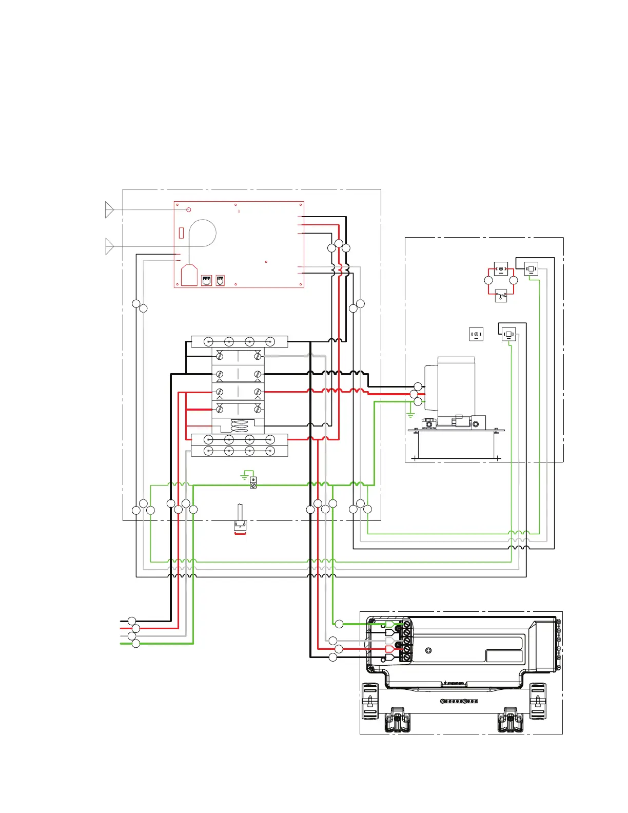
28
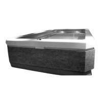
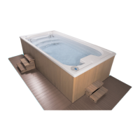
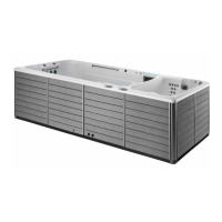
HEATER-CONTROLLER WIRING - ELITE POOL
Locate the electrical whip provided in the Hydraulic/Electrical Connections Kit. Remove one of the unused knockouts at
the bottom of the Hydraulic Power Unit Controller enclosure and secure the whip end to the open knockout. Connect the
black wire (Line 1) to terminal block T3. Connect the red wire (Neutral) to terminal block T2. Connect the white wire (Line
1) to the R1 terminal on the load side of the contactor. Connect the green wire (Ground) to the ground/earth terminal at
the base of the enclosure.
Run the opposite end of the whip to the Heater-Controller. Remove the front cover of the controller by removing the screws.
Connect the whip to the opening on the left side of the controller. Connect the black wire to the L1 terminal. Connect the
red wire to the N terminal. Connect the white wire to the L2 terminal. Connect the green wire to the G terminal.
Proceed to Heater-Controller Accessory Wiring.
Float
Level
Switch
Proportional
Valve
HYDRAULIC POWER UNIT
Hydraulic Power
Unit (HPU)
RR
Wifi
Antenna
RF
Antenna
WIFI
DISPLAY
KEYPAD
LEARN
ANT1
LINE 1 IN
OIL SIG +
OIL SIG -
SWITCHED OUT
AUX
SOL -
SOL +
(NEUTRAL) LINE 2 IN
T1
T2
T3
T1
T2
T3
R2
2
4
R4
Contactor and
Terminal Blocks
R1 NC
1 NO
R3 NC
3 NO
A2 A1
EP3 CONTROLLER
GECKO IN.YE HEATER CONTROLLER
LEARN SW
Line 1
Neutral
Spare
Ground
Single
Phase
Input
Line 1
Ground
Neutral
Line 1
W
W
W
W
W
W
WW
BB
B
BB
B
B
B
B
B
R
R
R
R
R
G/Y
G/Y
G/Y
G/Y
G/Y
G/Y
Line 1
Neutral
Ground
B
G/Y
GROUND
R
G
L3
L2
N
L1
B
REVISION:
EP-3 SOLO, CIRCUIT SAVER, GECKO IN.YE, 7.5 HP,
1 PH, 50 HZ
DRAWING/PART NUMBER:
WD0053
WIRING DIAGRAM
NOTES:
SEE HEATER CONTROLLER ACCESSORY
1.
FOR GECKO POWER JUMPER (PJ1 & PJ2)
CONFIGURATIONS