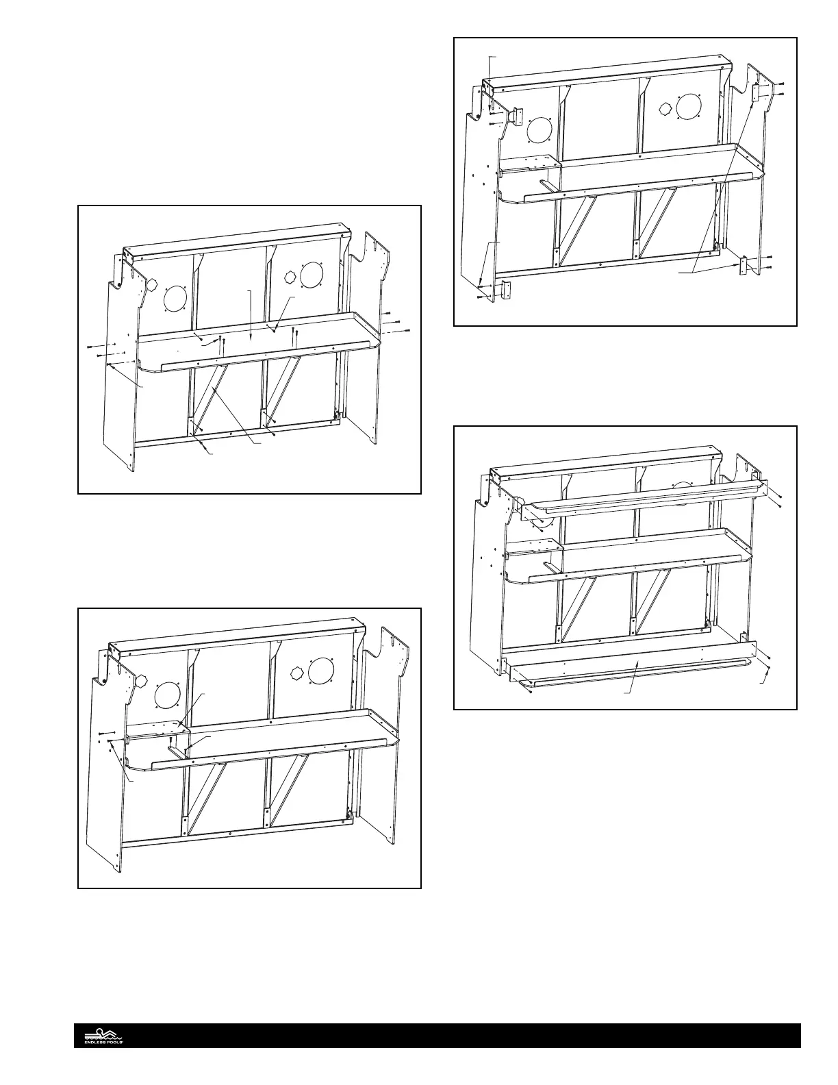
Align the pre-drilled holes in each diagonal support with the
pre-drilled holes on the at surface of the tray. Attach the diag-
onal supports to the underside of the equipment tray using the
(4) 1" (25mm) truss head screws located in the diagonal support
hardware bag. Attach the other ends of the diagonal supports
to the vertical panel stieners using the (4) self-drilling screws
located in the diagonal support hardware bag. Fig. 9.
Verify the equipment tray is level and attach the equipment tray
to the panel stieners with the (2) self-drilling screws located in
the equipment tray hardware bag. Fig. 9.
Diagonal
Support
Self-Drilling
Screw
Self-Drilling
Screw
Flat Head
Screw
Equipment
Tray
Truss Head
Screw
Fig. 9
Attach the pump support to the vertical support and equipment
tray. Use the (2) 1" (25mm) at head screws to attach the pump
support to the vertical support and the (2) 1" (25mm) truss head
screws to attach the pump support to the equipment tray located
in the pump support hardware bag. Fig. 10.
Flat Head
Screw
Truss Head
Screw
Pump Support
Fig. 10
Attach the support beam attachments to each vertical support.
Use the 1" (25mm) at head screws for the bottom support
beam attachments and the 1" (25mm) truss head screws for
the top support beam attachments located in the support beam
hardware bag. Fig. 11.
Support Beam
Attachment Angle
Flat Head
Screw
Truss Head
Screw
Fig. 11
Position and attach the upper and lower support beams to the
PVC support beam attachments using 1" (25mm) truss head
screws located in the support beam hardware bag. Fig 12.
Truss Head
Screw
Support Beam
Fig. 12
Install the thru-wall tting (drain tting) in the drain port of the
equipment tray. Make sure there is a black rubber gasket installed
between the tting and the top side of the equipment tray and
a cork gasket installed between the underside of the equipment
tray and the locknut. Note: e second black gasket that comes
with the thru-wall tting can be discarded. Fig. 13.
10