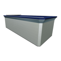
From the backside of the front pool panel, position the propul-
sion system suction and pressure thru-wall assemblies so the
holes in the corners of the square PVC plates align with the holes
around the large cut outs in the pool panel. Fig. 29.
Fig. 29
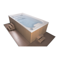
Insert the (4) hex head screws, located in the thru-wall hardware
bag, in the small holes in the panel. Install a washer on each bolt
and secure the bolts with the nuts provided. Fig. 30.
Nut
Washer
Hex Head Screw
Fig. 30
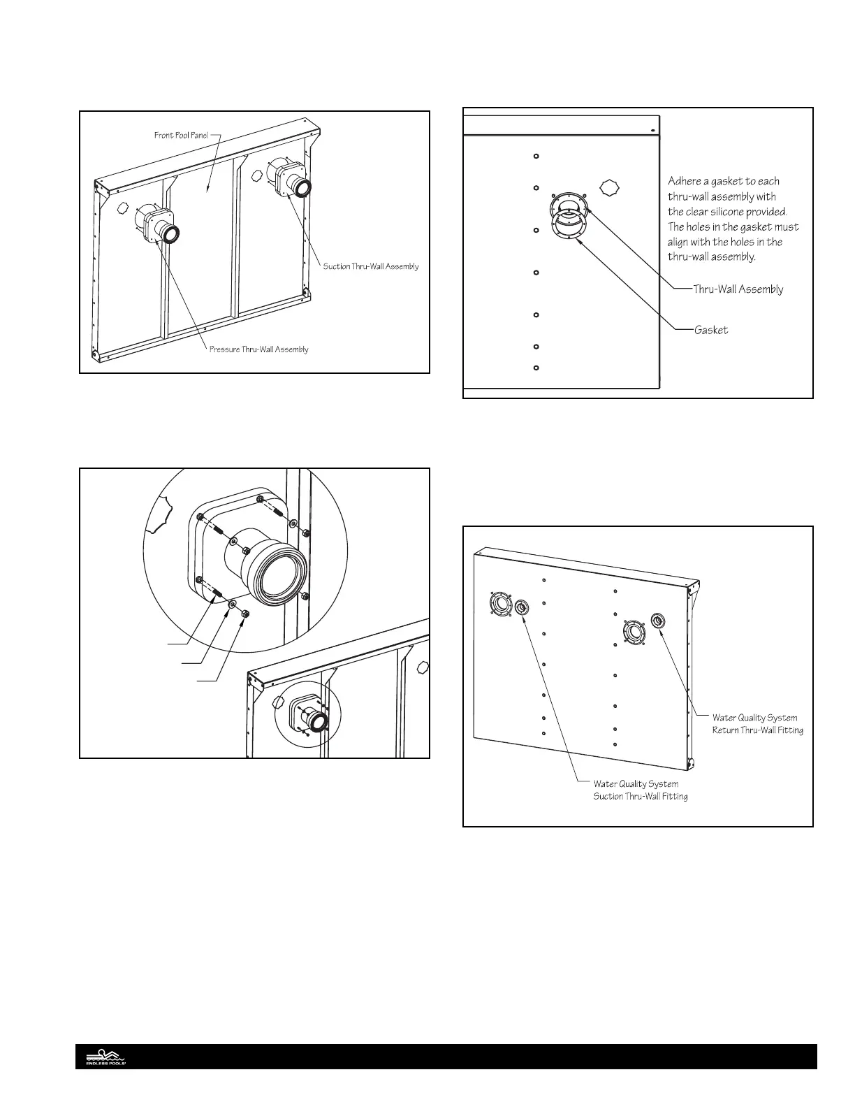
Adhere a large black gasket, located in the hardware kit, to
each thru-wall assembly using a thin bead of clear
silicone. Make sure the small holes in the gasket align with
the holes in the thru-wall assembly. Fig. 31.
Fig. 31
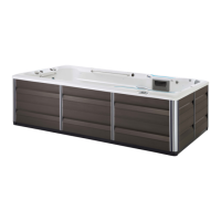
From the inside of the front pool panel, insert the water quality
system suction and return thru-wall ttings in the star cutouts
on the front panel. Fig. 32. Position the ttings so the holes are
in the twelve, three, six and nine o’clock positions. Secure these
ttings with locknuts on the backside of the panel.
Fig. 32
16