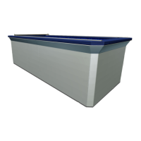
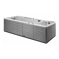
Carefully rotate and position the propulsion system housing so
it’s parallel with the front wall of the pool. Fig. 55
Fig. 55
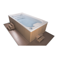
Align the internal pressure assembly (attached to the pressure
thru-wall assembly) to the pressure assembly that’s attached to
the propulsion system housing. Once aligned, tighten the union
to attach the assemblies. Fig. 55.1. If the two pressure assemblies
do not align vertically, an adjustment can be made to lower or
raise the propulsion system plumbing assembly (see “Propulsion
System Plumbing Height Adjustment”).
Internal Pressure
Assembly Union
Fig. 55.1
Propulsion System Plumbing Height Adjustment
Carefully move the propulsion system housing far enough away
from the front wall of the pool to gain access to the rear of the
unit. e height adjustment is located at the bottom rear of the
housing. Although not required, the water level can be partially
drained if necessary.
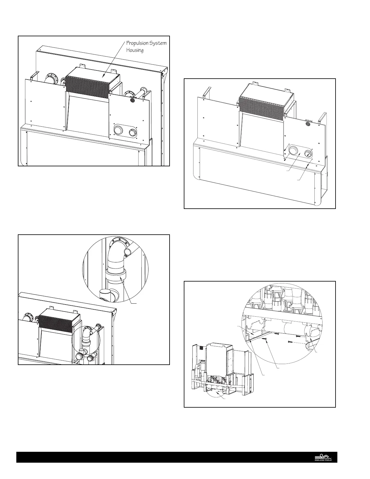
Remove the (4) screws that secure the escutcheon to the propul-
sion system housing. Fig. 55.2.
Escutcheon
Screws (X4)
Fig. 55.2
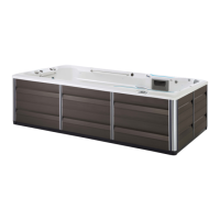
Locate the (2) cradles at the rear of the propulsion system hous-
ing towards the bottom of the unit. ere are (2) adjustment
screws that are in the center adjustment holes of each cradle.
Remove each adjustment screw. e plumbing assembly can be
lowered by utilizing the top adjustment holes. e plumbing as-
sembly can be raised by utilizing the lower adjustment holes. Re-
install the screws in the appropriate adjustment holes. Fig. 55.3.
Access for Height Adjustment
Adjustment Screw
Adjustment Holes
Cradle
Cradle
Fig. 55.3
23