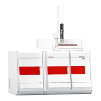
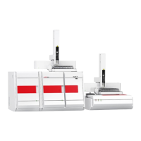
multi X 2500 Contents
3
Contents
1 Basic information ............................................................................................................. 7
1.1 User manual notes ...................................................................................................... 7
1.2 Intended use ............................................................................................................... 8
1.3 Warranty and liability.................................................................................................. 8
2 Safety instructions ........................................................................................................... 9
2.1 General notes .............................................................................................................. 9
2.1.1 Safety labeling on the multi X 2500 ........................................................................... 9
2.2 Requirements for the operating personnel ............................................................... 10
2.3 Safety instructions, transport and commissioning .................................................... 10
2.4 Safety instructions - operation .................................................................................. 11
2.4.1 General...................................................................................................................... 11
2.4.2 Safety instructions - electrical equipment ................................................................. 11
2.4.3 Safety instructions for compressed gas containers and systems ............................... 12
2.4.4 Handling of auxiliary and operating materials .......................................................... 13
2.4.5 Safety instructions: service and repair ....................................................................... 13
2.5 Safety equipment / Behavior during emergencies .................................................... 14
3 Function and layout of the multi X 2500 ..................................................................... 15
3.1 Principle of operation ................................................................................................ 15
3.2 Measuring methods .................................................................................................. 16
3.2.1 General information .................................................................................................. 16
3.2.2 AOX determination ................................................................................................... 16
3.2.3 EOX determination .................................................................................................... 17
3.2.4 POX determination ................................................................................................... 17
3.3 System design ........................................................................................................... 17
3.4 Layout of the multi X 2500 ....................................................................................... 18
3.4.1 Electronic components .............................................................................................. 18
3.4.2 Gas supply / measuring gas transfer ......................................................................... 21
3.4.3 Combustion system ................................................................................................... 24
3.4.4 Measuring gas drying in the standard version .......................................................... 26
3.4.5 Auto-protection assembly (optional) ........................................................................ 26
3.5 Chlorine module multi X 2500 .................................................................................. 28
3.5.1 Connections and interfaces ....................................................................................... 30
3.5.2 Measuring cell "sensitive" (default) ........................................................................... 31
3.5.3 Measuring cell "high concentration" .......................................................................... 33
3.5.4 Measuring cell "high sensitive" .................................................................................. 33
3.5.5 Measuring gas transfer and measuring gas drying (optional versions) .................... 37
3.6 Autosampler / sample introduction systems ............................................................. 38
3.6.1 autoX 36 / autoX 36d ............................................................................................... 39
3.6.2 Manual boat feed (MBD) .......................................................................................... 41
3.7 Pre-combustion adapter ........................................................................................... 41
4 Installation and commissioning ................................................................................... 43
4.1 Installation conditions ............................................................................................... 43
4.2 Energy supply ............................................................................................................ 43
4.3 Gas supply ................................................................................................................. 44
4.4 Space requirement and device layout ....................................................................... 44
4.5 Setting up and connecting the analyzer .................................................................... 46
4.6 Connecting additional system components ............................................................... 48
5 Operation ........................................................................................................................ 49
5.1 Switching on the analyzer ......................................................................................... 49
5.2 Switching off the analyzer ......................................................................................... 50
5.3 Restarting the analyzer after an emergency shutdown ............................................. 51
 Loading...