multi X 2500 Contents
5
14.1 Technical data ......................................................................................................... 122
14.2 Guidelines and standards ........................................................................................ 124
Figures
Fig. 1 Front view (with open doors) ........................................................................... 18
Fig. 2 Front view with status LED................................................................................ 19
Fig. 3 Rear view multi X 2500 ..................................................................................... 19
Fig. 4 Electrical interfaces on the rear of the multi X 2500 ...................................... 20
Fig. 5 Device control and interfaces in the device interior ........................................ 20
Fig. 6 Connection for the auto-protection assembly ................................................. 21
Fig. 7 Gas connections at the rear of the device ........................................................ 22
Fig. 8 Gas box ............................................................................................................... 22
Fig. 9 Gas connections on the open combustion tube (vertical operating mode) ... 23
Fig. 10 Connections on the multi-purpose combustion tube in horizontal mode . 23
Fig. 11 Combustion furnace in the vertical and horizontal operating mode .......... 24
Fig. 12 Open combustion tube .................................................................................. 24
Fig. 13 Combustion tube filled with used quartz containers ................................... 25
Fig. 14 Multi-purpose combustion tube ................................................................... 25
Fig. 15 Sulfuric acid container (vertical) in the standard version ........................... 26
Fig. 16 Auto-protection assembly ............................................................................. 27
Fig. 17 Toggle switch to lock/release combustion tube .......................................... 27
Fig. 18 Cl module in the standard version ................................................................ 29
Fig. 19 Connections on the rear of the chlorine module ......................................... 30
Fig. 20 Terminal on the internal wall of the chlorine module ................................ 31
Fig. 21 Measuring cell "sensitive" with lid ................................................................. 31
Fig. 22 Loaded measuring cell "sensitive" ................................................................. 32
Fig. 23 Electrode for "sensitive" & "high concentration" measuring cells ................ 32
Fig. 24 Measuring cell "high concentration" ............................................................. 33
Fig. 25 Measuring cell "high sensitive" ...................................................................... 34
Fig. 26 Loaded measuring cell "high sensitive" ......................................................... 34
Fig. 27 Sensor electrode ............................................................................................. 35
Fig. 28 Pt electrode with salt bridge (generator cathode) ...................................... 35
Fig. 29 Silver electrode (generator anode) ............................................................... 36
Fig. 30 Chlorine module with measuring cell "high sensitive" ................................. 36
Fig. 31 Sulfuric acid container with outlet in the chlorine module ......................... 37
Fig. 32 Gas inlet tube for the measuring cell "high sensitive" ................................. 38
Fig. 33 Introducing gas to the measuring cell (multi-purpose combustion tube) . 38
Fig. 34 Autosampler autoX 36 ................................................................................... 39
Fig. 35 autoX 36 (stacked on the multi X 2500) ...................................................... 40
Fig. 36 autoX 36d with ejection position .................................................................. 40
Fig. 37 Sample racks................................................................................................... 40
Fig. 38 Manual boat feed (MBD) .............................................................................. 41
Fig. 39 Pre-combustion adapter ................................................................................ 42
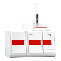
Fig. 40 Vertical operating mode with autoX 36d ..................................................... 44
Fig. 41 Vertical operating mode with autoX 112 ..................................................... 45
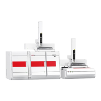
Fig. 42 Horizontal operating mode with ABD and autoX 112 ................................ 45
Fig. 43 Connection transfer line – sulfuric acid container with outlet .................... 68
Fig. 44 Hose diagram POX determination ................................................................ 83
 Loading...