Wiring Cerabar M HART
20 Endress+Hauser
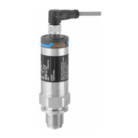
4.1.4 Connecting the valve connector M16, ISO4400
P01-PMx4xxxx-04-xx-xx-xx-009
Fig. 21: BN = brown, BU = blue, GNYE = green/yellow
4.2 Connecting the DXR375 handheld terminal
• For a Cerabar M with an FM or CSA certificate, perform the electrical connection in accordance
with the "control drawing" (provided in the packaging for Cerabar M).
• To transfer the communication signal without errors, there must be a communication resistor of
at least 250 Ω between the connection points and the power supply.
P01-PMx4xxxx-04-xx-xx-xx-014
Fig. 22: ➀ Any connection devices.
The handheld terminal can be connected anywhere along the 4 to 20 mA cable. Use an intrinsically safe voltage
source in Ex ia areas (e.g. RN221N).
1 23
1 2
+
-
BN BU GNYE
Cerabar M
4...20 mA
4...20 mA
1
2
3
4...20 mA
+
-
4...20 mA
min. 250 W
I
O
FMD 230:LIC0001
Online
1 >Group Select
2 PV 20 mbar
HELP
I
O
FMD 230:LIC0001
Online
1 >Group Select
2 PV 20 mbar
HELP
1 2
+ –
3
Zero
Damping
on off
Span
Display
➀

 Loading...


