Wiring
14
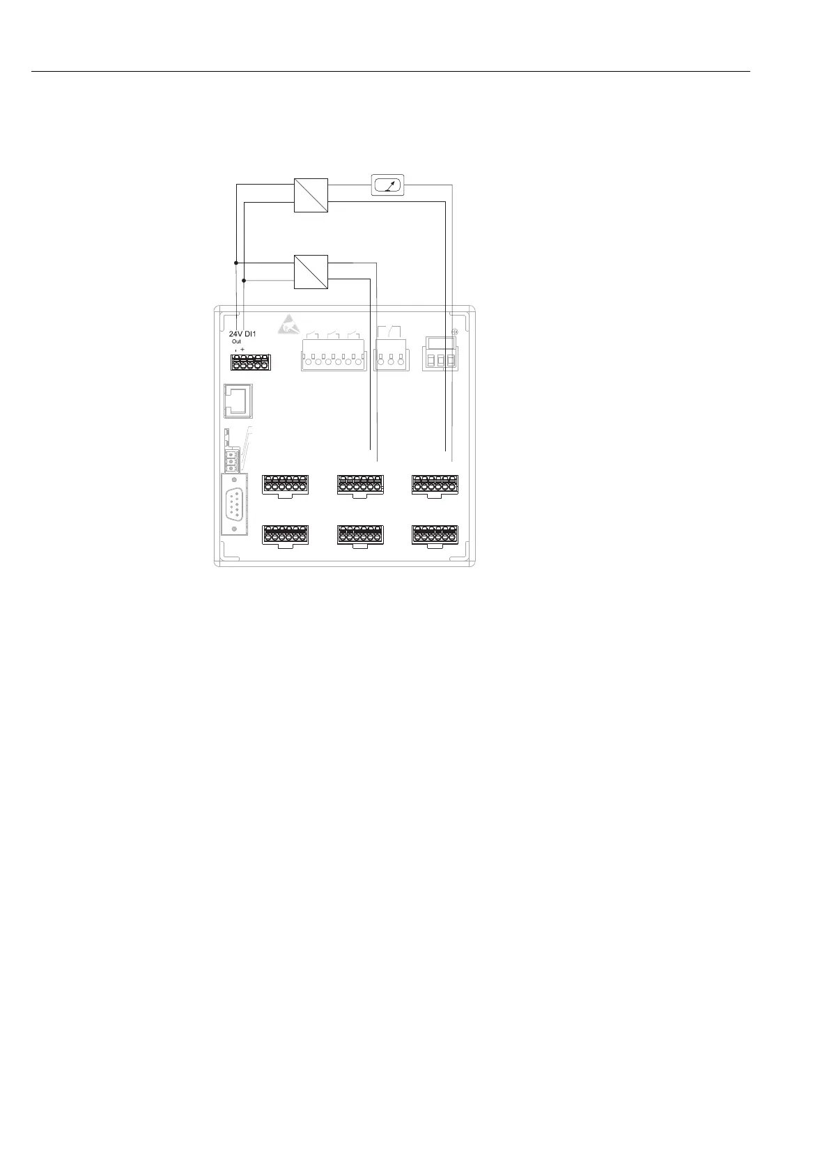
4.1.4 Auxiliary voltage output for 4-wire sensors
Fig. 7: Using the auxiliary voltage output as power supply for 4-wire sensors (at current measurement range)
4.2 Terminal assignment
"
Caution!
If high-energy transients occur when using long signal cables, we recommend connecting a suitable
overvoltage protection (e.g. E+H HAW560/562).
Use shielded signal lines for serial interfaces!
4.2.1 Cable specification, spring terminals
All connections on the rear of the unit are designed as screw or spring terminal blocks with reverse
polarity protection. This makes the connection very quick and easy. The spring terminals are
unlocked with a slotted screwdriver (size 0).
Please note the following when connecting:
• Digital I/O wire cross-section, RS485 and analog inputs: max. 1.5 mm
2
(14 AWG) (spring
terminals)
• Power wire cross-section: max. 2.5 mm
2
(13 AWG) (screw terminals)
• Relay wire cross-section: max. 2.5 mm
2
(13 AWG) (spring terminals)
• Stripping length: 10 mm (0.39 in)
!
Note!
No ferrules have to be used when connecting flexible wires to spring terminals.
5
6
9
1
GND
RxD/TxD +
RxD/TxD -
Ethernet
RS232
Rel2
41
42
31
32
21
22
11
13
12
L+
N-
PE
Rel4 Rel3
Rel1
RS485
CH 4 CH 5 CH 6
611
612
613
614
615
616
411
412
413
414
415
416
CH 1
CH 2
CH 3
111
112
113
114
115
116
211
212
213
214
215
216
311
312
313
314
315
316
511
512
513
514
515
516
DI3
93
92
91
_
+
-
Y
+
+
_
+
-
Y
Out: max. 250 mA
On connecting channels 1-4 see
terminal connections CH 5-6
Sensor 1 e.g. TR13 from E+H
Sensor 2
Ext. display
(optional)
e.g. RIA261 from E+H
 Loading...