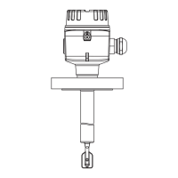
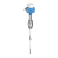
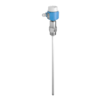
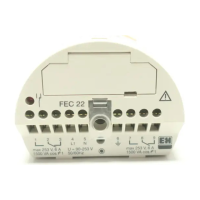
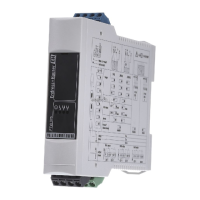
Liquiphant FTL64
12 Endress+Hauser
Terminal assignment
L1 N
4
3 5
8
7
6
U = 19...55 V DC
U 19...253 V AC
~
~
!
0.5 A
1
2 2
L1
L+
NO NONC NCC CN
L-
PE
1 2 3 64 75 8
MIN
>0,7
MAX
>0,5
COM
A0036062
7 Universal current connection with relay output, electronic insert FEL64
1 When bridged, the relay output works with NPN logic
2 Connectable load
Behavior of switch output
and signaling
3 54
3 54
6 87
6 87
3 54
3
3
5
5
4
4
6 87
6
6
8
8
7
7
MAX
RD YE GN
MIN
A0033513
8 Behavior of switch output and signaling, electronic insert FEL64
MAXDIP switch for setting MAX safety mode
MIN DIP switch for setting MIN safety mode
RD LED red for alarm
YE LED yellow, switch status
GN LED green, operational status, device on

 Loading...


