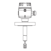
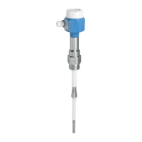
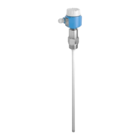
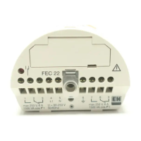
Liquiphant FTL64
Endress+Hauser 37
Elements on the electronic
insert
MIN
>0,7
MAX
>0,5
COM
U = 9...20 V DC
4
3 5 8
7
6
L-L+
1
2
3
4
5
6
7
8
1
2
3
4
5
6
7
8
9
A0037705
46 Example of electronic insert FEL64DC
1 COM interface for additional modules (LED module, Bluetooth module)
2 LED, red, for warning or alarm
3 LED, yellow, switch status
4 LED, green, operational status (device is on)
5 Test button, activates functional test
6 Terminals (3 to 8), relay contact
7 DIP switch for configuring density, 0.7 or 0.5
8 DIP switch for configuring MAX/MIN safety mode
9 Terminals (1 to 2), power supply
Terminals
Terminals for cable cross-section up to 2.5 mm
2
(14 AWG). Use ferrules for the wires.
Local operation Operation at electronic insert
MAX/MIN fail-safe mode
A0033470
47 Switch position on the electronic insert for fail-safe mode MAX/MIN
A MAX (maximum fail-safe mode)
B MIN (minimum fail-safe mode)
• Minimum/maximum quiescent current safety can be switched at the electronic insert
• MAX = Maximum safety: When the tuning fork is covered, the output switches in the direction of
demand. Use this for overfill prevention, for example.
• MIN = Minimum safety: When the tuning fork is uncovered, the output switches in the direction of
demand. Use this for dry-running protection of pumps, for example.
Density switchover
A0033471
48 Switch position on the electronic insert for density
Factory setting for density: 0.7

 Loading...


