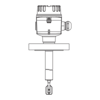
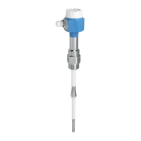
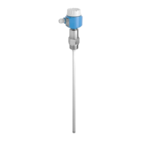
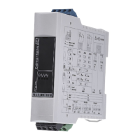
Liquiphant FTL64
20 Endress+Hauser
(Water +23 °C (+73 °F)).
Minimum distance between the fork tip and the tank wall or pipe wall: 10 mm (0.39 in)
~13 (0.5)
~5 (0.2)
~12.5 (0.49)
D
A B C
D
D
A0044069
17 Typical switch points. Unit of measurement mm (in)
A Installation from above
B Installation from below
C Installation from the side
D Switch point
Measured error
At reference operating conditions: –1 to +1 mm (–0.04 to +0.04 in)
Hysteresis
At reference operating conditions: 2.5 mm (0.1 in)
Non-repeatability
At reference operating conditions: 0.3 mm (0.01 in)
Influence of the process
temperature
The switch point moves between +1.4 to –5.5 mm (+0.06 to –0.22 in) in the temperature range
from –60 to +280 °C (–76 to +536 °F)
Influence of the process
pressure
The switch point moves between 0 to –3.9 mm (0 to –0.15 in) in the pressure range from
–1 to +100 bar (14.5 to 1 450 psi)
Installation
Open the device only in a dry environment!
Mounting location,
orientation
• Any orientation for device with short pipe up to approx. 500 mm (19.7 in)
• Vertical orientation for device with long pipe
• Minimum distance between the fork tip and the tank wall or pipe wall: 10 mm (0.39 in)

 Loading...


