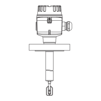
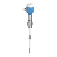
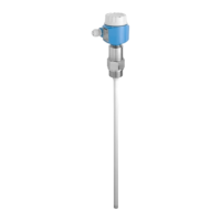
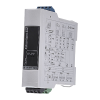
Liquiphant FTL64
16 Endress+Hauser
Behavior of switch output
and signaling
MAX
RD YE GN
MIN
1
1
1
1
1
2
2
2
2
2
L+
L+
L+
L+
L+
150 Hz
50 Hz
50 Hz
150 Hz
0 Hz
L-
L-
L-
L-
L-
A0037696
12 Switching behavior and signaling, electronic insert FEL67
MAXDIP switch for setting MAX safety mode
MIN DIP switch for setting MIN safety mode
RD LED red for alarm
YE LED yellow, switch status
GN LED green, operational status, device on
The switches for MAX/MIN on the electronic insert and the FTL325P switching unit must be
set according to the application. Only then is it possible to perform the functional test correctly.
2-wire NAMUR > 2.2 mA/ < 1.0 mA (electronic insert
FEL68)
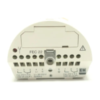
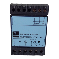
• For connection to the isolating switch repeater as per NAMUR (IEC 60947-5-6), e. g. Nivotester
FTL325N from Endress+Hauser
• Signal transmission H-L edge 2.2 to 3.8 mA/0.4 to 1.0 mA as per IEC 60947-5-6 (NAMUR) on
two-wire cabling
• Functional testing without level change. A functional test can be performed on the device using
the test button on the electronic insert or using the test magnet (can be ordered as an option) with
the housing closed.
The functional test can also be triggered by interrupting the supply voltage or activated directly
from the Nivotester FTL325N.
Supply voltage
U = 8.2 V
DC
Pay attention to the following as per IEC/EN61010-1: Provide a suitable circuit breaker for the
device.
Power consumption
NAMUR IEC 60947-5-6
Behavior of output signal
• OK status: output current 2.2 to 3.8 mA
• Demand mode: output current 0.4 to 1.0 mA
• Alarm: output current 1.0 mA

 Loading...


