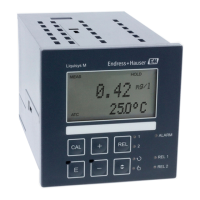
A0009055-EN
Set value is an absolute value.
This function is primarily
suited to batch operation and
single-sided limit switches.
7.4.7 Relay configuration
For the "RELAY" function group, you require a relay card which is not available in the basic
device version.
The following relay contacts can be selected and configured as desired (max. four contacts,
depending on options installed):
• Limit contactor for conductivity measured value: R2 (1)
• Limit contactor for temperature: R2 (2)
• PID controller: R2 (3)
• Timer for cleaning function: R2 (4)
• Chemoclean function: R2 (5)
• USP/EP: R2 (6) and R2 (7) (for Plus Package, only conductive sensors)
Limit contactor for conductivity measured value and temperature
The transmitter has different ways of assigning a relay contact. Switch-on and switch-off
points and pickup and dropout delays can be assigned to the limit contactor. In addition,
you can configure an alarm threshold to output an error message and to start a cleaning
function in conjunction with this.
These functions can be used both for the primary value and for temperature measurement.
Please refer to the switch states in → 29 for a clear illustration of the relay contact
states.
• When the measured values increase (maximum function), the relay contact is closed as
of t2 after the switch-on point (t1) has been exceeded and the pickup delay has elapsed
(t2-t1).
The alarm contact switches if the alarm threshold (t3) is reached and the alarm delay
(t4-t3) has also elapsed (errors E067 to E070).
• When the measured values decrease, the alarm contact is reset when the value falls
below the alarm threshold (t5) again, as is the relay contact (t7) after the dropout delay
(t7-t6).
• If the pickup and dropout delays are set to 0 s, the switch-on and switch-off points are
also switch points of the contacts.
The same settings can also be made for a minimum function in the same way as for the
maximum function.
 Loading...
