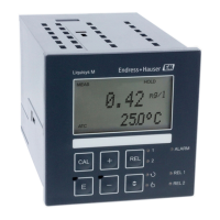
Maintenance Liquisys M CLM223/253
94 Endress+Hauser
9.1.6 Checking inductive sensors
The following applies to the CLS50, CLS52 and CLS54 sensors.
The sensor cables must be disconnected at the device or junction box for all tests described
here!
• Testing the transmitting and receiving coils:
Perform the measurement at the white and red coaxial cables, between the inner
conductor and shield in each case.
– Ohmic resistance
CLS50/52: approx. 0.5 to 2 Ω
CLS54: approx. 1 to 3 Ω
– Inductance approx. 180 to 500 mH (for 2 kHz, series circuit as equivalent circuit
diagram)
CLS50: approx. 250 to 450 mH
CLS52/54: approx. 180 to 550 mH
• Testing the coil shunt:
A shunt is not permitted between the two sensor coils (from red coax to white coax). The
measured resistance must be > 20 MΩ.
Test with the ohmmeter from the red coax cable to the white coax cable.
• Temperature sensor test:
Use the table in the "Simulation of conductive sensors for device testing" section to check
the Pt 100 / Pt 1000 in the sensor.
Measure between the green and white wires and between the green and yellow wires.
The resistance values must be identical.
• Temperature sensor shunt test:
Shunts are not permitted between the temperature sensor and the coils. Check with
ohmmeter for > 20 MΩ
Measure between the temperature sensor wires (green + white + yellow) and the coils
(red and white coax).
9.1.7 Assembly
Refer to the assembly operating manual for information on servicing and troubleshooting
the assembly. The assembly operating manual describes the procedure for mounting and
disassembling the assembly, replacing the sensors and seals, and contains information on
the material resistance properties, as well as on spare parts and accessories.
9.1.8 Connecting cables and junction boxes
• Use the methods described in chapters "Simulation of conductive/inductive sensors for
device test" to perform a quick functional check from the conductivity sensor (sensor
connector) to the measuring instrument via an extension. The easiest way to connect
resistor decades is with the "Conductivity testing adapter" service kit, order number:
51500629
• Check junction boxes for:
– Moisture (influence at low conductivity or for MΩ measurement, where necessary dry
box, replace seals, insert dehydrating bag)
– Correct connection of all lines
– Connection of the outer shields
– Tightness of the terminal screws
 Loading...
