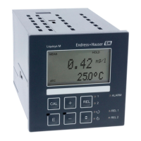
Maintenance Liquisys M CLM223/253
92 Endress+Hauser
With the Pt 1000 type of temperature sensor, all the resistance values are increased by a
factor of 10.
Attach the temperature equivalent resistor in a three-wire system.
Conductivity
If the cell constant k is set to the value in column 2 of the following table, then the
conductivity values of this table apply.
Otherwise the following applies: Conductivity [mS/cm] = k[cm
-1
] ⋅ 1 / R[kΩ]
Resistance R Cell constant k Display for conductivity Display for MΩ
10 Ω 1 cm
-1
100 mS/cm
10 cm
-1
1000 mS/cm
100 Ω 0.1 cm
-1
1 mS/cm 1 kΩ ⋅ cm
1 cm
-1
10 mS/cm
10 cm
-1
100 mS/cm
1000 Ω 0.1 cm
-1
0.1 mS/cm 10 kΩ ⋅ cm
1 cm
-1
1 mS/cm
10 cm
-1
10 mS/cm
10 kΩ 0.01 cm
-1
1 μS/cm 1 MΩ ⋅ cm
0.1 cm
-1
10 μS/cm 100 kΩ ⋅ cm
1 cm
-1
100 μS/cm
10 cm
-1
1 mS/cm
100 kΩ 0.01 cm
-1
0.1 μS/cm 10 MΩ ⋅ cm
0.1 cm
-1
1 μS/cm 1 MΩ ⋅ cm
1 cm
-1
10 μS/cm
1 MΩ 0.01 cm
-1
0.01 μS/cm 100 MΩ ⋅ cm
0.1 cm
-1
0.1 μS/cm 10 MΩ ⋅ cm
1 cm
-1
1 μS/cm
10 MΩ 0.01 cm
-1
0.001 μS/cm
0.1 cm
-1
0.01 μS/cm 100 MΩ ⋅ cm
The MΩ measurement is normally used for pure and ultrapure water and therefore
only makes sense for cell constants k= 0.01 cm
-1
or k = 0.1 cm
-1
.
9.1.4 Simulation of inductive sensors for device testing
The inductive sensor cannot be simulated.
However, the overall system comprising the transmitter and inductive sensor can be tested
using equivalent resistors. Note the cell constant k (e.g. k
nominal
= 1.98 cm
-1
for CLS50,
k
nominal
= 5.9 cm
-1
for CLS52, k
nominal
= 6.3 cm
-1
for CLS54).
For accurate simulation, the actual cell constant used (visible in field C124) must be used
to calculate the display value.
The formula for calculation also depends on the type of sensor:
• CLS50 and CLS52: conductivity reading [mS/cm] = k[cm
-1
] ⋅1/R[kΩ]
• CLS54: conductivity reading [mS/cm] = k[cm
-1
] ⋅1/R[kΩ] ⋅ 1.21
 Loading...
