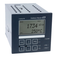
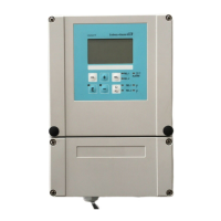
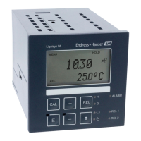
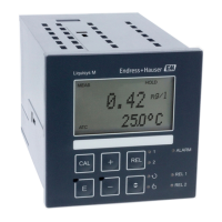
Repair Liquisys M CLM223/253
98 Endress+Hauser
Item Kit description Name Function/contents Order no.
330, 400 Housing module Housing with front membrane, sensory
tappets, seal, special screw, tensioning
dogs, connection plates and nameplates
51501075
340 End frame
PROFIBUS-DP
Rear frame for PROFIBUS DP, with D-
submin plug connector
51502513
345 Grounding terminal strip PE and shielding terminals 51501086
420a,
420b
Terminal strip set Complete terminal strip set, standard +
HART
51501203
420a,
420b
Terminal strip set Complete terminal strip set
PROFIBUS PA
51502126
420a,
420b
Terminal strip set Complete terminal strip set
PROFIBUS DP
51502493
430 Terminal strip Terminal strip for relay module 51501078
A Fuse Part of power unit, item 15
B Choice of line voltage Position of jumper on power unit, item
15 depending on line voltage
10.3 Disassembling the field device
Please note the effects on the process if the device is taken out of service!
See the exploded drawing for the item numbers.
You require the following tools to disassemble the field device:
• Standard set of screwdrivers
• Torx screwdriver, size TX 20
Proceed as follows to disassemble the field device:
1. Open and remove the cover of the connection compartment (item 420).
2. Disconnect the supply terminal (item 470) to de-energize the device.
3. Open the display cover (item 410) and release the ribbon cables (item 310/320) on
the central module side (item 40 to 91) .
4. To remove the central module (item 40) release the screw in the display cover (item
450 b).
5. Proceed as follows to remove the electronics box (item 330):
6. Turn the screws in the housing base (item 450 a) by two revolutions to release them.
7. Then push the entire box backwards and remove it from above while making sure
that the module locks do not open.
8. Release the ribbon cables (item 310/320).
9. Bend the module locks out and remove the modules.
10. To remove the docking module (item 340) remove the screws in the housing base
(item 450 c) and remove the entire assembly from above.
11. To remove the conductivity transmitter (item 240) nip off the heads of the synthetic
distance sleeves using a fine wire cutter.
12. Then remove the module from above.
 Loading...
