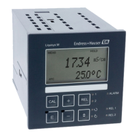
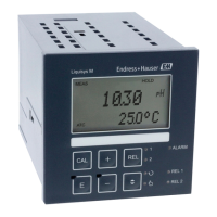
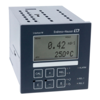
Liquisys M CLM223/253 Commissioning
Endress+Hauser 79
Coding Field Range of
adjustment
(factory
settings in
bold)
Display Info
C124 The calculated cell
constant is
displayed
0.0025 to 99.99
cm
-1
A0009152-EN
The calculated cell constant
is displayed and accepted in
A5.
C125 Calibration status
is displayed
o.k.
E xxx
A0009153-EN
If the calibration status is
not o.k., a reason for the
error is provided on the
second line of the display.
C126 Store calibration
result?
Yes
No
New
A0009154-EN
If C125 = E xxx, then only
No or New.
If New, return to C.
If Yes/No, return to
"Measurement".
C1(3) Calibration with
sensor adjustment
for inductive
sensors (only for
Plus Package)
Airs = air set (1)
Cellc = cell
constant (2)
InstF =
installation
factor (3)
A0009144-EN
Sensor adjustment with
compensation for wall
effects.
In the case of inductive
sensors, the measured value
is influenced by the distance
between the sensor and the
pipe wall and by the
material of the pipe
(conductive or insulating).
The installation factor
indicates these
dependencies. See the
Technical Information of
the sensor used for more
information
The inductive sensor is mounted at the place of
installation.
A0025599
C131 Enter the process
temperature (MTC)
25 °C
-35.0 to 250.0 °C
A0009155-EN
Only available if B1 = fixed.
C132 Enter the α value of
the calibration
solution
2.10 %/K
0.00 to 20.00
%/K
A0009156-EN
The value is given in the TI
for all E+H calibration
solutions. You can also use
the printed-on table to
calculate the value.
Set α to 0 for calibration
with uncompensated values.
C133 Enter the correct
conductivity value
of the calibration
solution
Current
measured value
0.0 μS/cm to
9999 mS/cm
A0009157-EN
A value close to the
subsequent operating range
should be selected.
 Loading...
