3 Mechanical installation RMS 621
12 Endress+Hauser
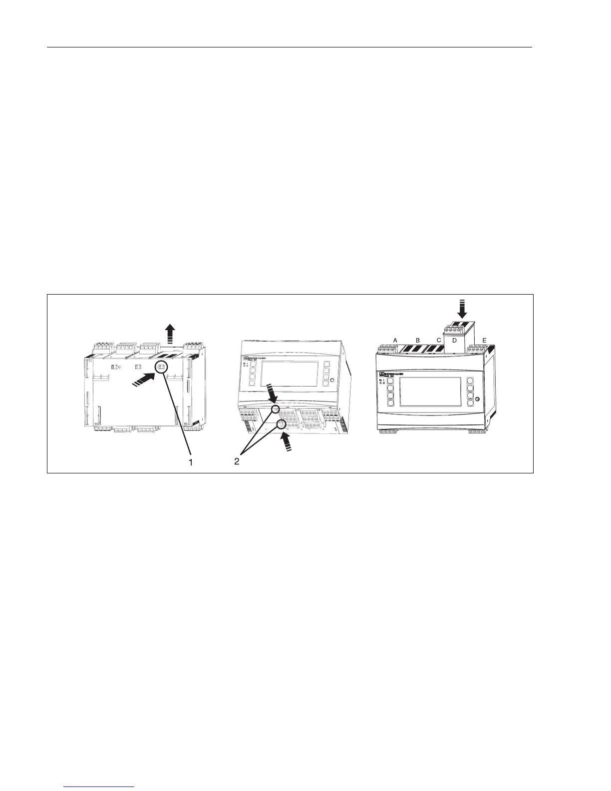
3.2.1 Installation of expansion cards
It is possible to fit various expansion cards into the unit. For this purpose there are a maximum of
three slots available. The expansion card plug in slots are identified as B, C and D (→ Fig. 5) on the
unit.
1. When installing or removing expansion cards to or from the unit, always make sure that the
power supply is OFF.
2. Remove the blanking plate from the required expansion slot in the unit. This is done by
pressing the holding clips on the bottom of the energy manager together (see Fig. 5, Pos. 2),
simultaneously push the holding clip on the back of the unit inwards (e.g. using a screwdriver)
(see Fig. 5, Pos. 1), then push the blank housing upwards out of the unit.
3. The expansion card is slotted into the unit from the top. The expansion card is only correctly
fitted when the holding clips on the lower and rear sides of the unit have clicked into place
(see Fig. 5, Pos. 1 and 2). Make sure that the input terminals of the expansion card are at the
top and the analogue connection terminals to the base unit are facing the front.
4. The new expansion card is automatically recognised by the unit once it has been correctly
connected and set up (see Chap. "Commissioning").
Fig. 5: Installing a new expansion card (example)
Pos. 1: Holding clip on unit base
Pos. 2: Holding clips on lower side of the unit
Pos. A - E: Slot allocation identification
!
Note!
If existing expansion cards are removed and not replaced, then the spaces must be filled by using
blanking cards.
3.3 Installation control
If using expansion cards, always make sure that they are correctly seated in the allocated slots of the
unit.
!
Note!
When using the unit as a heat counter, take note of installation regulations EN 1434 Part 6. This
includes the installation of the flow and temperature sensors.