4 Electrical installation RMS 621
14 Endress+Hauser
!
Note!
The current/PFM/pulse inputs or RTD inputs in the same slot are not galvanically separated. There
is an isolation voltage of 500 V between the above inputs and outputs installed in different slots.
Terminals having the same identity are internally linked.
4.2 Connecting measurement sensors
"
Caution!
Do not install/connect the unit under power. If this is ignored it can lead to total damage of parts
of the electronics.
131 + 0/4 to 20 mA/pulse output 1 E bottom back (E IV) Current/pulse output 1
132 - 0/4 to 20 mA/pulse output 1
133 + 0/4 to 20 mA/pulse output 2 Current/pulse output 2
134 - 0/4 to 20 mA/pulse output 2
52 Relay common (COM) A bottom front (A III) Relay
53 Relay normally open (NO)
92 +24 V sensor supply Additional sensor supply
91 Supply ground
L/L+ L for AC
L+ for DC
A bottom back (A IV) Power supply
N/L- N for AC
L- for DC
RS232 Interface 3.5 mm jack plug socket
on front
Remote set up from PC
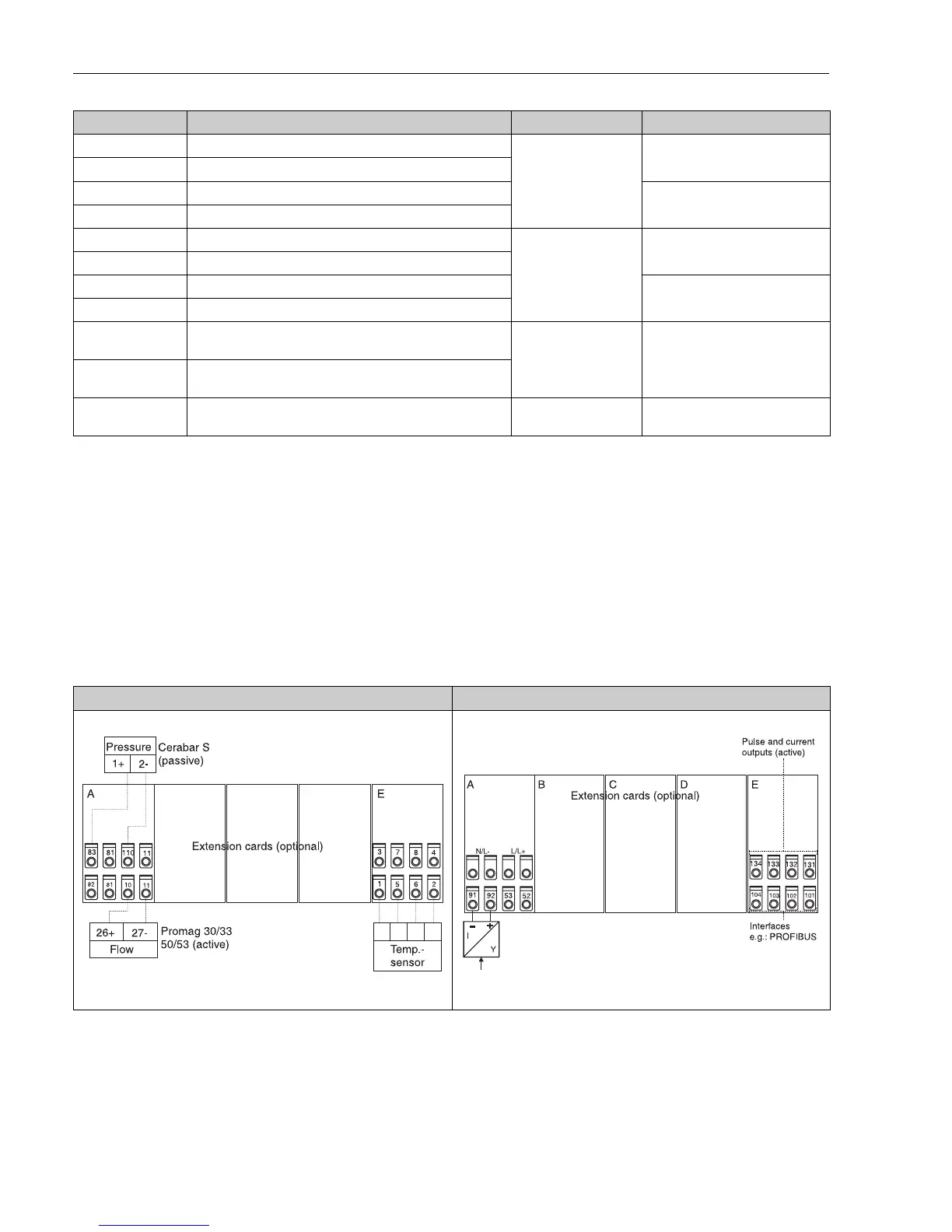
Terminal (Pos.no.) Terminal layout Slot In- and output
Top of unit connection view (inputs) Bottom of unit connection view (outputs, interfaces)