RMS 621 4 Electrical installation
Endress+Hauser 15
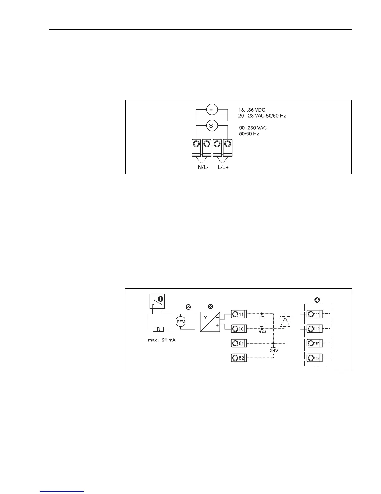
4.2.1 Power supply connection
"
Caution!
• Before installing the unit make sure that the supply to be used corresponds with that shown on
the unit legend plate.
• When operating with a 90 to 250 V AC (power supply) a power isolator must be situated within
easy reach of the unit. This should be fuse protected using a current rating of ≤ 10 A.
Fig. 7: Power supply connection
4.2.2 Connecting external sensors
!
Note!
Both active and passive sensors with analogue, PFM, or pulse signals and RTD sensors can be
connected to the unit.
Dependent on the signal type, the terminals can be freely selected. This means that the energy
manager is very flexible in its application and the terminals are not bound to any particular sensor
type, e.g. flow sensor terminal 11, pressure sensor terminal 12 etc. If the unit is to be used as a heat
counter according to the OIML R 75, then the connection regulations contained in that norm are
valid.
Active sensors
Connection of an active sensor (this means external power supply).
Fig. 8: Connection of an active sensor, e.g. to input 1 (Slot AI)
Pos. 1: Pulse signal
Pos. 2: PFM signal
Pos. 3: 2-wire transmitter (4-20 mA)
Pos. 4: Connection of an active sensor, e.g. optional universal expansion card (Slot B I,
→
Fig. 13)