5 Operation RMS 621
24 Endress+Hauser
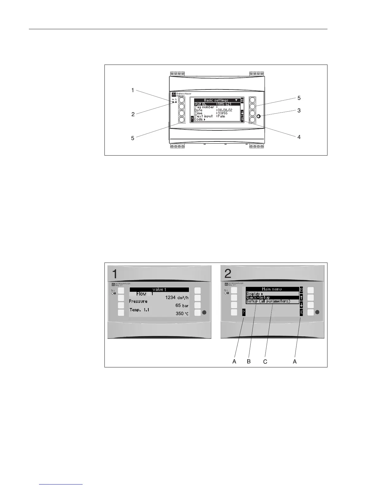
5.2 Human interface
Fig. 17: Display and operating elements
Pos. 1: Operational display: Green LED, illuminates when power supply is active.
Pos. 2: Fault condition display: Red LED, operating conditioning according to NAMUR NE 44.
Pos. 3: Serial interface connection: Jack plug socket for PC connection to the unit in order to set up and read out measured
values from the unit using the PC software
Pos. 4: Display 132 x 64 dot-matrix display with interactive dialogue text for set-up and display of the measured values,
alarm set points and fault messages. The rear illumination can be set up to change from blue to red in a fault condition.
The displayed character size is dependent on the number of parameters to be displayed
(see chap. 6.4.3 "Display set-up").
Pos. 5: Entry keys; Eight soft keys, the function of each key changes depending on the menu address. The actual functionality
of the key is always indicated on the display. Only the keys required in any particular operating menu are displayed
with their individual function.
5.2.1 Display
Fig. 18: Energy manager display functions
Pos.: 1: Measured value display
Pos.: 2: Set-up menu address display
– A: Key symbols
– B: Active set-up menu
– C: Selection of active set-up menu (black highlight).