RMS 621 4 Electrical installation
Endress+Hauser 19
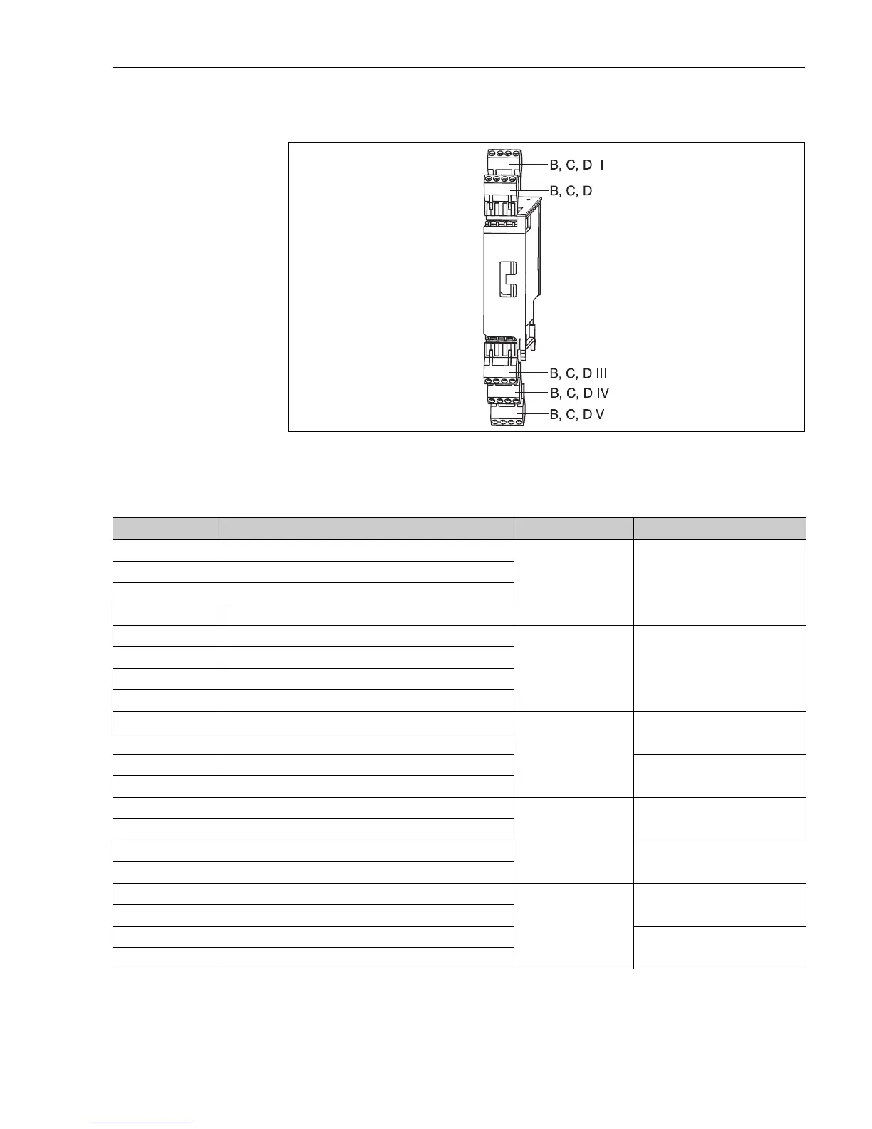
4.2.4 Connecting expansion cards
Fig. 13: Expansion cards with terminals
Terminal layout of universal input expansion card (RMS621A-UA)
Terminal (Pos.no.) Terminal layout Slot In- and outputs
182 24 V power supply 1 B, C, D top front (B I, C I,
D I)
Current/PFM/pulse input 1
181 Ground power supply 1
112 + 0/4 to 20 mA/PFM/pulse input 1
111 Signal ground for 0/4 to 20 mA/PFM/pulse input
183 24 V power supply 2 B, C, D top back (B II, C
II, D II)
Current/PFM/pulse input 2
181 Ground power supply 2
113 + 0/4 to 20 mA/PFM/pulse input 1
111 Signal ground for 0/4 to 20 mA/PFM/pulse input
142 Relay 1 Common (COM) B, C, D bottom front (B
III, C III, D III)
Relay1
143 Relay 1 normally open (NO)
152 Relay 2 Common (COM) Relay 2
153 Relay 2 normally open (NO)
131 + 0/4 to 20 mA/pulse output 1 B, C, D bottom middle (B
IV, C IV, D IV)
Current/pulse output 1 active
132 - 0/4 to 20 mA/pulse output 1
133 + 0/4 to 20 mA/pulse output 2 Current/pulse output 2 active
134 - 0/4 to 20 mA/pulse output 2
135 + Pulse output 3 (Open collector) B, C, D bottom back (B V,
C V, D V)
Passive pulse output
136 - Pulse output 3
137 + Pulse output 4 (Open collector) Passive pulse output
138 - Pulse output 4