Modbus Integrator's Guide for the Cordex® CXC HP Controller | 3 - Using Modbus
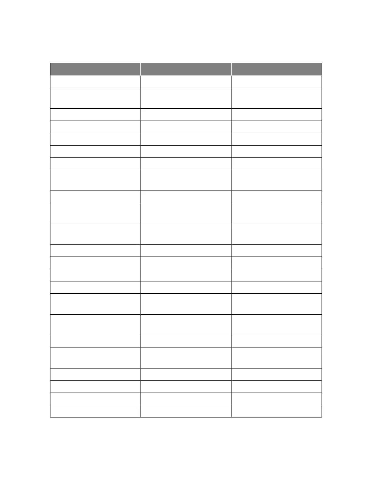
Table 3-30 AMPS HP modular inverter system data points (continued)
Name Register Format
Supported by All Inverters 04:Input Register 32-bit Floating Point
Expected DC Input Current in AC
Failure
04:Input Register 32-bit Floating Point
Highest Phase Power % of Use 04:Input Register 32-bit Floating Point
Phase 1 AC Output Power (VA) 04:Input Register 32-bit Floating Point
Phase 1 Output Voltage 04:Input Register 32-bit Floating Point
Phase 1 Output Current 04:Input Register 32-bit Floating Point
Phase 1 Output Frequency 04:Input Register 32-bit Floating Point
Phase 1 Phase Power (VA) % of
Use
04:Input Register 32-bit Floating Point
Phase 1 Number Of Inverters On 04:Input Register 32-bit Floating Point
Phase 1 Phase Power (W) % of
Use
04:Input Register 32-bit Floating Point
Phase 1 Measured DC Input To
Output Power Ratio
04:Input Register 32-bit Floating Point
Phase 1 AC Input Power (W) 04:Input Register 32-bit Floating Point
Phase 1 AC Input Power (VA) 04:Input Register 32-bit Floating Point
Phase 1 AC Output Power (W) 04:Input Register 32-bit Floating Point
Phase 1 DC Input Power 04:Input Register 32-bit Floating Point
Phase 1 Current Number Of Re-
dundant Inverters
04:Input Register 32-bit Floating Point
Phase 1 Number of Inverters De-
tected
04:Input Register 32-bit Floating Point
Phase 1 Number Of Inverters Off 04:Input Register 32-bit Floating Point
Phase 1 Number Of Inverters
Failed
04:Input Register 32-bit Floating Point
Phase 2 AC Output Power (VA) 04:Input Register 32-bit Floating Point
Phase 2 Output Voltage 04:Input Register 32-bit Floating Point
Phase 2 Output Current 04:Input Register 32-bit Floating Point
Phase 2 Output Frequency 04:Input Register 32-bit Floating Point
Page 36 0350114-J0 Rev N
 Loading...