0922001-J0 Rev A
30
User GuideCordex® CXPS-E105 Edge Power Systems
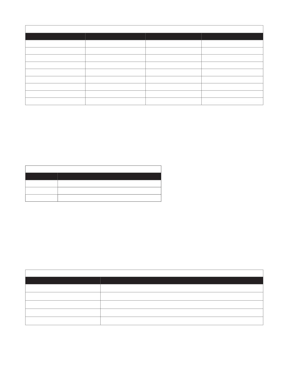
Table E — Cable size equivalents (AWG to Metric)
Cable size Circular mils Square millimeters Equivalent metric cable
00 AWG (or 2/0) 133100 67.42 70
0000 AWG (or 4/0) 211600 107.2 120
313 MCM (or kcmil) 313600 159 150 or 185
350 MCM (or kcmil) 350000 177.36 185
373 MCM (or kcmil) 373700 189 185 or 240
500 MCM (or kcmil) 500000 253.36 300
535 MCM (or kcmil) 535300 271 300
750 MCM (or kcmil) 750000 380.00 400
777 MCM (or kcmil) 777700 394 400
7.1. 2 Recommended torque values
Table F lists the recommended torque values for connection to the power system with the following hardware:
• Clear hole connections (nut and bolt)
• PEM studs
• PEM threaded inserts
• Thread formed connections (in copper busbar)
Grade 5 rated hardware is required for these torque values.
Table F — Recommended torque values
Size Torque value
1/4 inch 11.93 Nm (8.8 ft-lb)
3/8 inch 44.06 Nm (32.5 ft-lb)
1/2 inch" 98.97 Nm (73 ft-lb)
7.2 Grounding
Connect the isolated power system battery return bus (BRB) to the building master ground bus (MGB), or
floor ground bus (FGB) in a larger building. This acts as a system reference and as a low impedance path to the
ground for surges, transients and noise. The MGB or FGB must have a direct low impedance path to the building
grounding system.
The cable from the power system to the MGB or FGB must be sized to provide sucient ampacity to clear the
largest fuse or breaker on the power system, excluding the battery protection fuse or circuit breaker. This is the
minimum requirement. Other factors including length of cable and special grounding requirements of the load
must also be factored in. The insulated cable must be equipped with two-hole crimp type lugs and must not have
any tight bends or kinks.
Table G — Typical ground reference conductor selection
Power system ampacity Recommended ground reference conductor size
<30 A 6 mm² (10 AWG)
30 A to 100 A 16 to 35 mm² (6 to 2 AWG)
100 A to 400 A 107 mm² (0000 AWG)
400 A to 800 A 185 mm² (350 MCM)
>800 A 400 mm² (750 MCM)
The power system frame must also be connected to the MGB or FGB. This is done for personnel safety and to
meet many Telecom grounding requirements. Each bay must have its own frame or site ground connection. Refer
also to the customer connections drawing at the end of this document.
 Loading...