0922001-J0 Rev A
34
User GuideCordex® CXPS-E105 Edge Power Systems
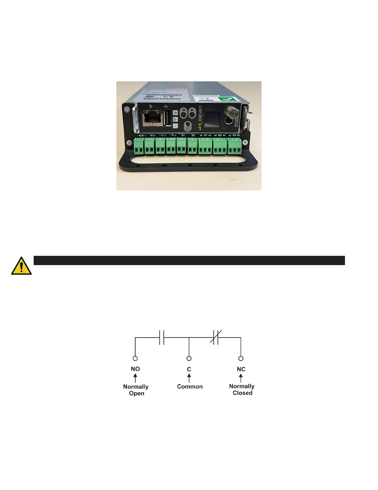
7.8 Alarm and signal connections
1. The terminal blocks are located below the controller. The power system is factory wired to the distribution
panel through the DB25 cable assembly. T1, K2 and K3 are available for customer connections.
2. Connect these alarms and signals to the local alarm-sending unit. Use wire sizes 1.5 to 0.14 mm² (16 to
26AWG).
7.9 Signal wiring connections for controller
Reference is made to drawings located at the rear of this manual. Custom configurations may be detailed within
the power system documentation package.
For terminal block connections, the recommended wire sizes are 1.5 to 0.14 mm
2
(16 to 26 AWG) for the
temperature range of 0 to 50°C (32 to 122°F) as per UL/CSA.
7.9.1 Alarm (relay) outputs
Terminals provide contacts for extending various alarm or control signals. Each relay output can be wired for
normally open (NO) or normally closed (NC) operation during an alarm or control condition.
Relays can be programmed to energize or de-energize during an alarm condition. See the controller software
manual. All relays will de-energize when the controller reset button is pressed or when the power is lost.
Figure 12: Alarm and signal connections
Figure 13: Relay connections
CAUTION
To reduce risk of fire, use only 0.14 mm² (26 AWG) or larger wire.
 Loading...