M
M
W
7.67
M
M
W
7.67
Battery Installation Manual
Pubication No: US-DDM-IM-AA - June 2016
SYSTEM LAYOUT
Before installing the battery system, lay out available floor
space including aisles for installation, maintenance and
possible cell replacement. Consult the local installation
considerations as determined in Section 5 of the Safety,
Storage, Operating and Maintenance Manual for the
VRLA Modular Battery Systems. Recommended minimum
clearance between these racks and any objects (including
walls and equipment) is 4 inches (102 mm).
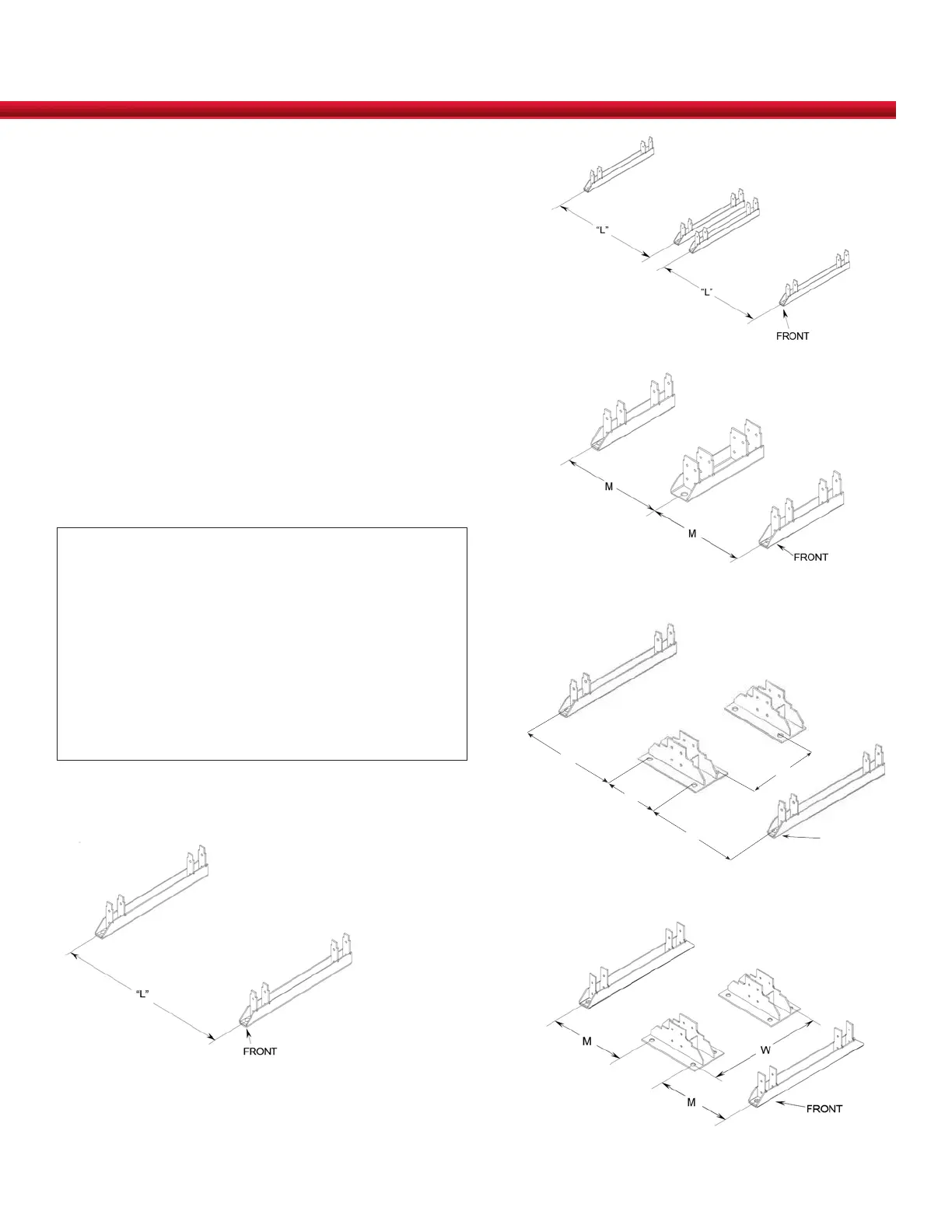
1. Layout the system position for either a SINGLE STACK
(Figure 4), a MULTI-STACK (Figure 5), or MULTI-
STACK WITH ZERO SEPARATION (Figures 6, 7 and 8)
configuration with the dimensions defined in Table 2.
2. Locate the position of the floor anchors using the frame
base beams.
NOTE:
• Floor anchoring is REQUIRED for all installations.
• Allow sufficient clearance between adjacent walls or
equipment for proper installation of anchors. Please
check your local codes for clearances required.
• Floor anchor design (including, but not limited to
size, quantity and capacity) and installation are the
responsibility of the user/installer.
• Follow the user’s design and the manufacturer’s
instructions.
3. Mark floor with the position of the floor anchors.
MULTI-STACK
FIGURE 5
DDm35/50 MULTI-STACK WITH ZERO SEPARATION
FIGURE 6
SINGLE STACK
FIGURE 4
DDm85/100 MULTI-STACK WITH ZERO SEPARATION
FIGURE 7
DDm125 MULTI-STACK WITH ZERO SEPARATION
FIGURE 8
9
D
D= Distance between
bases (variable)
W= DDm85=17.46
DDm100=20.47
FRONT
 Loading...