POWER FACTOR CONTROLLER
RG3-12C/CS
Warnings :
1.3 Rear Panel
4
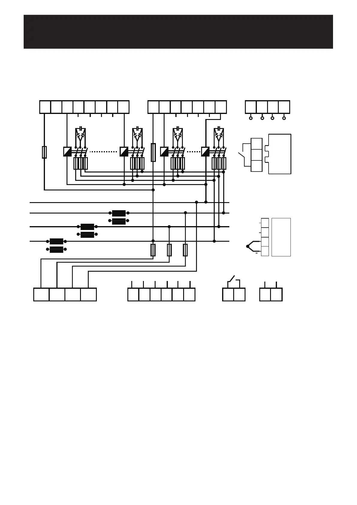
CONNECTION DIAGRAM
* Current value of 3-Phase fuses, which are connected to protect the capacitors, must be chosen according to the nominal
current value of capacitors which are given by the manufacturer.
** Optional.
15 16 17 18 19 20 21
5 6 7 8 9 10
K L
K
L
K L
6A
Alarm Relay
11 12
C1 C6 C7 C12
22 23 24 25 26 27 28
2A 2A 2A
k1
l1
k2 l2 k3 l3
k1
l2k2
l3k3
l1
29 30 31 32
N
L3
L2
L1
****
Generator
Input
13 14
110~250 V AC
1 2 3 4
L1 L2 L3 N
First, connection type of auxiliary supply, voltage measurement and current measurement input must be 3 phase-neutral. The
device will not operate properly if these connections are not done.
After the device is energized, it finds connection errors and corrects automatically as the first operation. Phase current should not be aqual
to zero in order to let the device to detect the connection error. Device detects the connection error according to Active Power direction.
Device switches ON and OFF the 1st steps 3-phase capacitor during the correction of connection errors (Phase sequence error and
polarity error of Current Transformer). Device may not correct the connection errors if there are too many instant variations for loads and
nonlinear loads (Such as Thyristor or triac controlled frequency inverter, UPS etc.). In this case, user should disconnect the device and restart
it to make the same operation. This feature also can also be operated with turning ON the Auto SET function in Auto menu. In this case
device corrects the errors and then calculates the capacitor values.
After connection errors are corrected; capacitor steps are calculated with turning ON the Auto Setup function in Auto menu (Refer to
Automatic Capacitor Recognition menu). A 3-phase capacitor has to be connected to 1st step of the device. All steps are measured
seperately if the program-10 (PS-10) is selected in Program menu. In this program (PS-10); single or 3-Phase capacitors can be connected
according to requirements of the system in any order. If you let the device calculate the step power values in the previous step, you can
skip this part.If one of the other programs is chosen, device measures the 1st steps power value and then calculates the other steps values
according to 1st steps value. Device calculates the capacitor values which will be switched ON according to selected program and switches
ON or OFF the necessary steps.
Connection of a circuit breaker or an automatic fuse is highly recommended between the network and RG3-12C/CS. This circuit
breaker must be marked in order to seperate them from other breakers.
All fuses which are used must be FF type and the current values of the fuses must be 2A or 3A and 6A (Refer to Connection Diagram).
The connection to the generator input of the device must be done in a way that the energy comes to the system after the generator
connection to the network has been established. Otherwise, the device will be switched to the generator operation for any generator
starts including the ones for maintaining purposes.
In order make a correct measurement, J type (Fe/Cu-Ni) thermocouple must be connected to TEMP terminal.
a)
b)
c)
d)
e)
f)
g)
Fan Relay
3837
**
33 34 35 36
J Type
Fe/Cu-Ni
+
**
TEMP.
GNDBTR A
RS485