EMW90HDNC1A Air-cooled Chiller
Step 3 Connect the coolant inlet and outlet pipes
of the chiller according to the screen
printing.
1. Connect the coolant outlet of chiller
with the coolant inlet of the equipment
to be cooled.
2. Connect the coolant inlet of chiller with
the coolant outlet of the equipment to
be cooled.
3.4 Electrical Connection
Prerequisites
Mechanical installation has been completed.
Precautions
Electrical connections must be operated by trained
When connecting the power cord, live operation is
The maximum operating current of the chiller is 32A.
Please install a C40 circuit breaker on the side of the
power distribution cabinet to ensure safe operation
and facilitate subsequent maintenance of the chiller.
In order to avoid any destructive influence, the chiller
must be grounded reliably before turning on the power
supply.
All electrical connections must meet the requirements
of national and local electrical codes.
Background
The user wiring interface of EMW90HDNC1A
chiller adopts fool-proof design, please refer to
Table 3-3 for details of the interface.
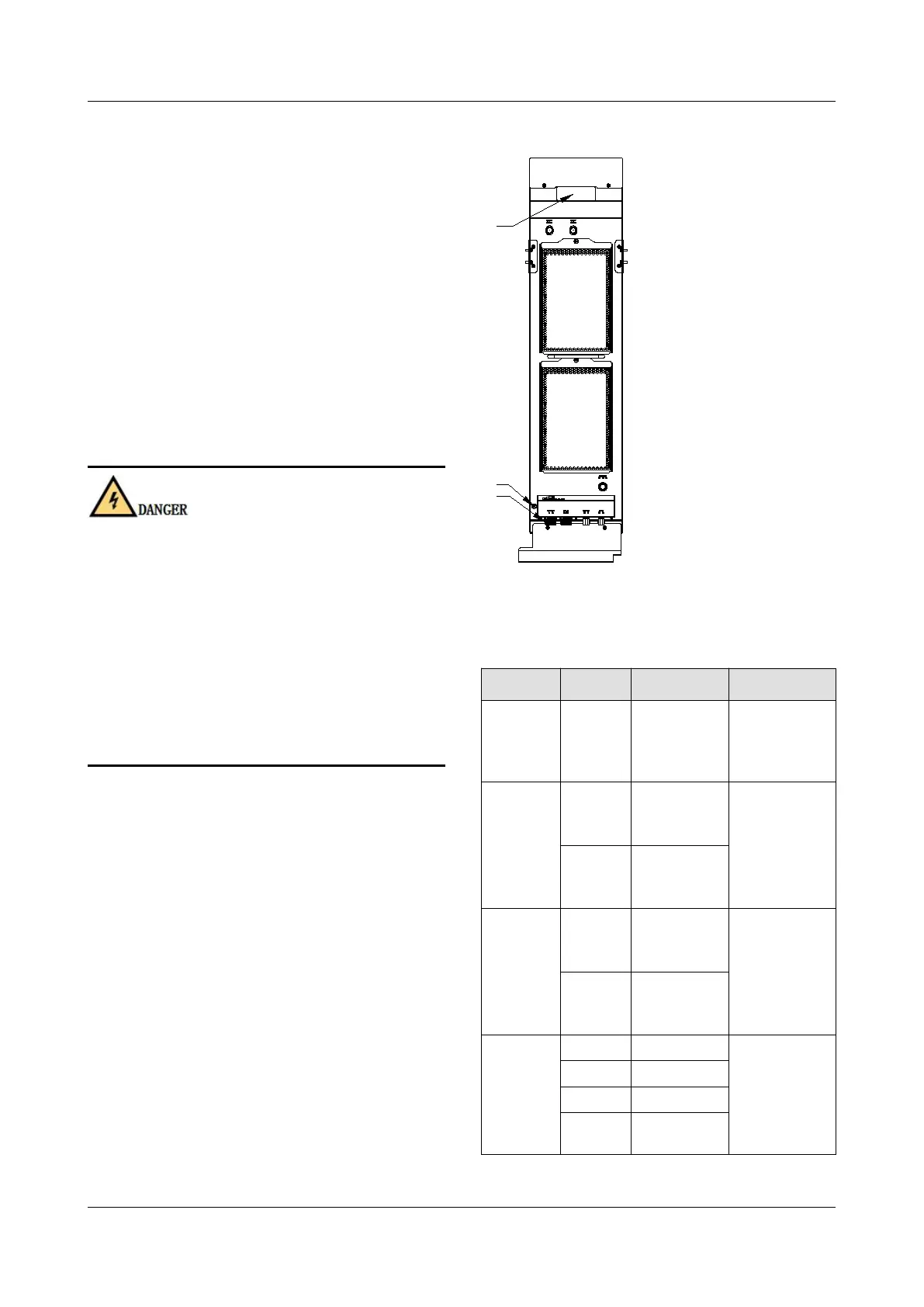
Figure 3-2 User wiring interface
Table 3-3 Definition of electrical interface pins
Single-pha
se power
supply L1
Input power
interface of
the chiller.
Single-pha
se power
supply L2
Single-pha
se power
supply L1
Power
interface of
the coolant
filling pump.
Single-pha
se power
supply L2
Field
communicat
or
communicat
ion
interface.