EMW90HDNC1A Air-cooled Chiller
The chiller supports the connection of a field
communicator (see Table 3-3 for wiring) to
provide users with a human-machine interface.
Users can query, set up and monitor conveniently
through the touch screen to ensure the normal
operation of the chiller.
Interface
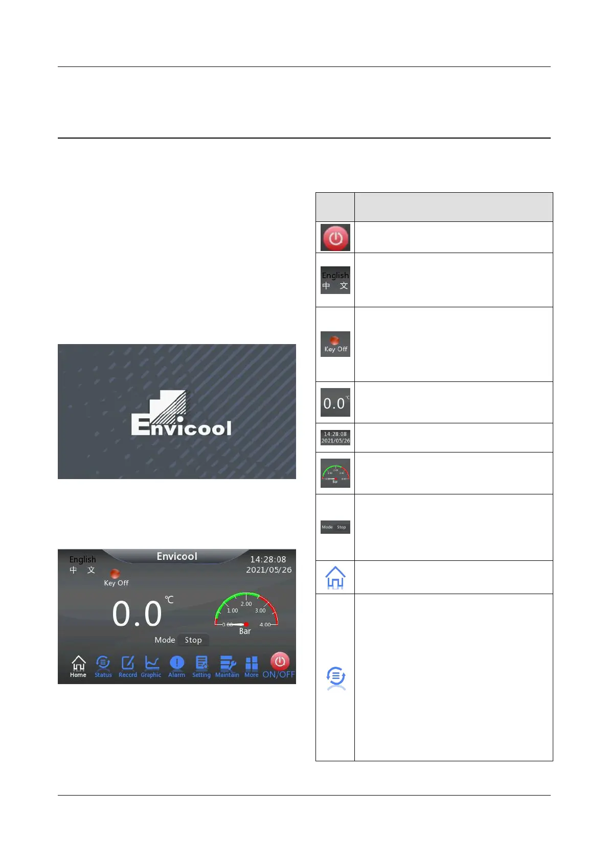
Turn on the power switch to power on the chiller,
the system is initialized, as shown in Figure 4-1.
Figure 4-1 System initialization interface
After the control system is initialized for about 10
seconds, it will enter the homepage interface of
the control system, as shown in Figure 4-2.
Figure 4-2 Control system homepage interface
After the system is powered on, press any key
and the backlit light will light up. If there is no
keyboard operation after a period of time, the
backlit light will dim.
The meanings of icons in the control interface of
the chillers are shown in Table 4-1.
Table 4-1 Control interface icons
Switch button icon, click to change the
current working state of chiller.
Display the language icon, and click it
to switch the language of the current
interface back and forth to Chinese or
English.
Working status icon, which displays the
current working status of water chillers
in the form of indicator lights.
Green indicates running status.
Red indicates the shutdown state.
Outlet water temperature icon, which
displays the outlet water temperature of
the current chiller (Unit: °C).
Date and time icon, showing the
current date and time of the unit.
Outlet pressure icon, which displays
the current outlet pressure of water
machine in the form of dial (Unit: Bar).
The system mode icon displays the
current operation mode of the system.
Running modes include: Stop, Cycle,
Cool, Heat and Auto. click the current
mode to switch to the next mode.
System main interface icon, click the
icon to enter the system main interface.
System status icon. Click the icon to
view the environment status, running
status and group control status.
Environmental conditions include
outlet water temperature, return water
temperature, indoor temperature and
humidity, outlet water pressure,
return water pressure, battery
maximum temperature, battery
minimum temperature, current grid
voltage, monitoring and dispatching
temperature, environmental
temperature and electronic control