Initial Installation
QUALIFIED INSTALLERS ONLY
intRoDuction:
This section of the owner’s manual is for the use of qualied technicians only. Fireplace placement, hearths,
facing, mantels, and venting terminations will be covered, as well as the gas and electric systems. There are
several installation safety guidelines that must be adhered to. Please carefully read the safety precautions
at the front of this manual.
NOTE: The Q1LI comes as a top vent unit but can be converted to a rear vent.
Warning: Clearances must be sufcient to allow access for maintenance and service.
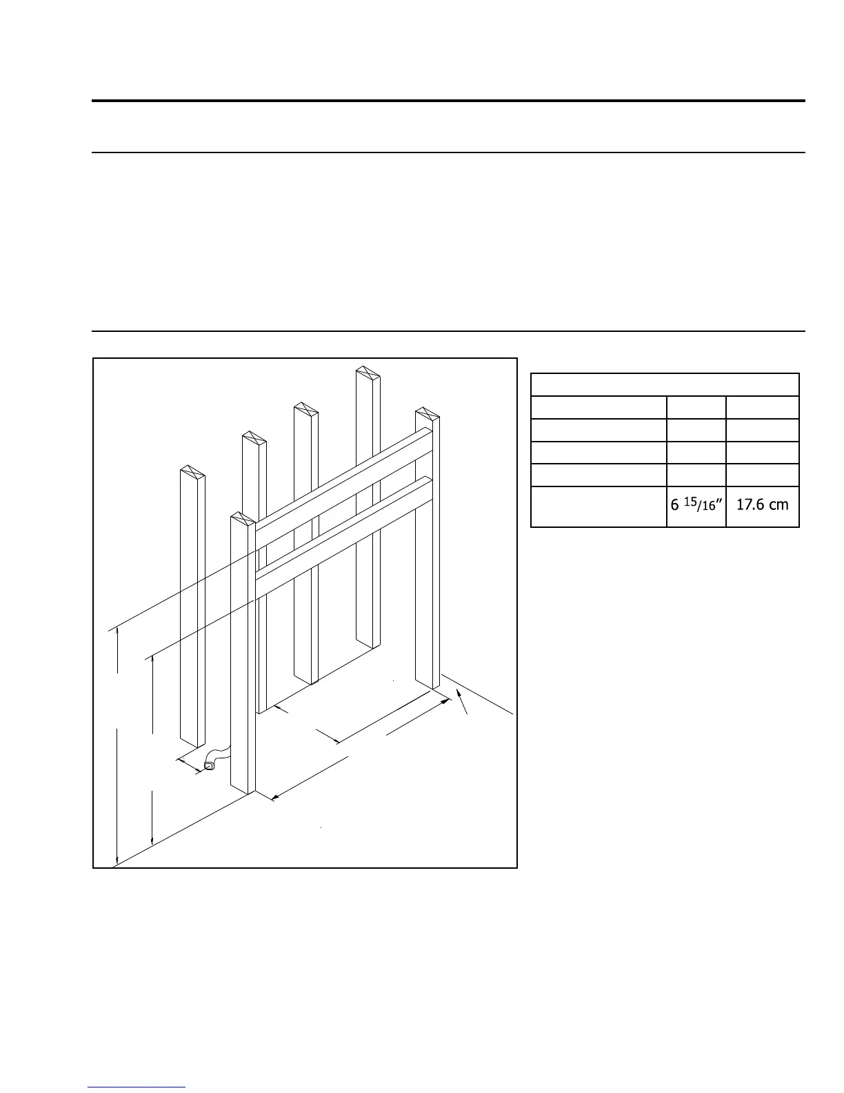
pLacement anD fRaming:
Table 2. Framing Dimensions.
Firebox Framing
Depth 15⅛” 38.4 cm
Width 25¼” 64.1 cm
Height - Rear Vent 35¼” 89.5 cm
Height - Top Vent 41” 104.1 cm
Gas Inlet (Distance
From Back)
The location for the replace can be
along a wall, raised or at oor level, or
in a corner. There are specic framing
measurements for each situation.
The basic opening should have the
dimensions shown in Figure 22.
The replace must have a strong and
level surface to be placed on. The
surface should be made of wood or a
non-combustible material, not carpet.
The framing boards may touch the
top and back standoffs, but only the
supplied insulating material can
be placed between the frame and
the standoffs.
The gas line, ⅜ inch NPT, should be
Figure 22. Dimensions for Framing the Firebox
19
Brought to the left side of the replace. The location should be chosen so the replace will be at least
36 inches (91.4 cm) from drapes, doors and other combustibles. The framed opening should also be a
minimum of 3 11/16” inches (9.4 cm) from the nearest perpendicular wall (sidewall to the edge of the
opening).
35
1
/4"
(895mm)
25
1
/4"
(641mm)
15
1
/8"
(384mm)
6
15
/16"
(176mm)
Gas
Inlet
Ad
j
ac
e
n
t
w
a
l
l
3
11
/16 "
min
(94mm)
Rear
Vent
Top
Vent
41"
(1041mm)