Maintenance 6. Joint #2
100 L
S20-B Rev.4
6.1 Replacing Joint #2 Motor
Maintenance
AC Servo Motor (520 W) 1 2197985
Tools
Hexagonal
width across flats: 2.5 mm
Cross-point screwdriver (#2)
A brake is mounted on the motor of Joints #3 and #4 to prevent the shaft from moving down
and rotating due to the weight of the end effector while the power to the Controller is OFF
or while the motor is in OFF status (MOTOR OFF).
Move the shaft down to its lower limit before the replacement procedure following the
removal steps.
Motor
Push down the shaft to its lower limit while pre
ssing the brake release switch.
Be sure to keep enough space and prevent
the end effector hitting any
peripheral
equipment.
The brake release switch is applied to both Joints #3 and Joint #4.
When the brake release switch is pressed, the respective brakes of the Joint #3 and Joint
#4
are released simultaneously.
shaft falling and rotating while the brake release switch is
because the shaft may be lowered by the weight of an end effector.
Arm Top Cover.
For details, refer to Maintenance: 3.1 Arm Top Cover.
and Duct Plate.
For details, refer to Maintenance: 3 Covers.
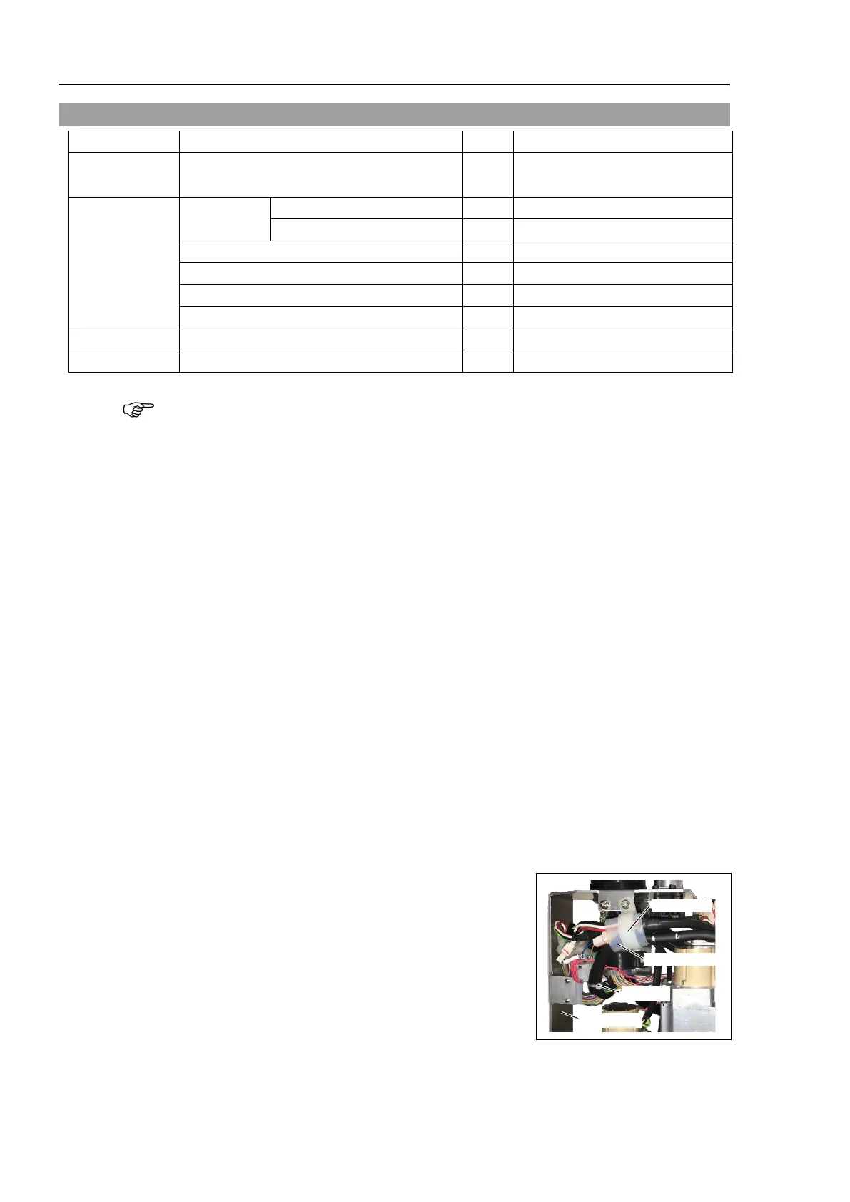
Remove the Clip Band and Sheet binding the
motor
cables.
The Clip Band and sheet will be reused
when
installing the cable unit.
Be careful not to lose them.
o not cut the wire tie (in the duct fittings outlet) that
binds the cables to the duct
plate.
Clip Band
Wire Tie
Duct Plate
Silicon Sheet
Disconnect the following connectors
.
Connectors: X221, X42 (Hold the clip to remove.)

 Loading...


