Maintenance 10. Ball Screw Spline Unit
LS20-B Rev.4 151
Screw
pline Unit
Push down the shaft to its lower limit while pre
ssing the brake release switch.
Be sure to keep enough space and prevent
the end effector hitting any
The brake release switch is applied to both Joints #3 and Joint #4.
When the brake release switch is pressed, the respective brakes of the Joint #3 and Joint
#4 are
released simultaneously.
shaft falling and rotating while the brake release switch is
because the shaft may be lowered by the weight of an end effector.
Detach the wires/tubes from
the end effector, and remove the end effector.
tep is only for Cleanroom-model.
Remove the bellows. For details, refer to Maintenance: 9. Bellows.
Arm Top Cover and Arm Bottom Cover.
For details, refer to Maintenance: 3. Covers.
parts:
Joint #3 motor unit Joint #4 motor unit
For details, refer to the following manuals:
Maintenance 7.1 Replacing Joint #3 Motor
Maintenance 8.1 Replacing Joint #4 Motor
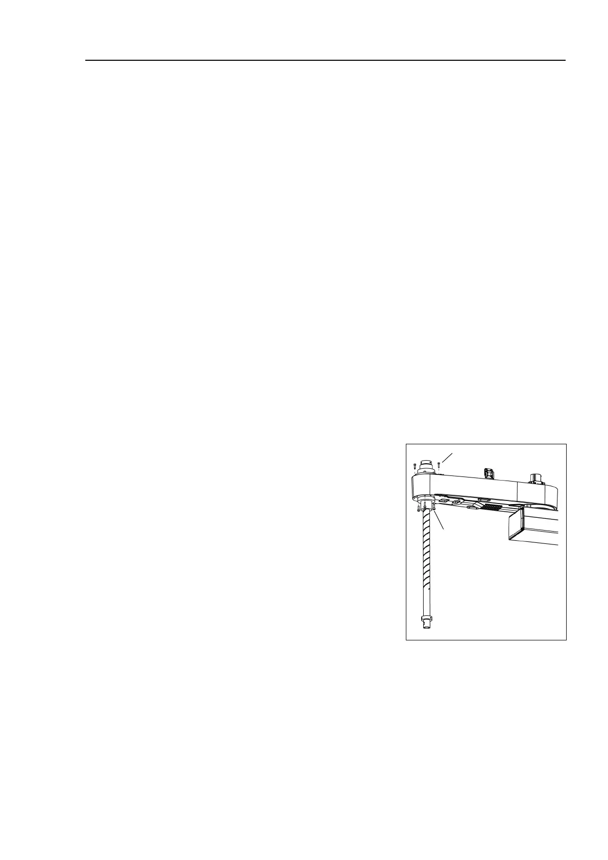
Remove three screws mounting the spline
plate.
Remove four screws mounting the spline nut.
)
Pull out the following toward the Arm #2 upper side.
Ball screw spline unit Z belt U belt

 Loading...


