EasyManuals Logo
Home>Epson>Robotics>LS20-B Series

Epson LS20-B Series User Manual

Epson LS20-B Series
188 pages
To Next Page IconTo Next Page
To Previous Page IconTo Previous Page
Page #183 background imageLoading...
Page #183 background image
Maintenance 13. Calibration
LS20-B Rev.4 171
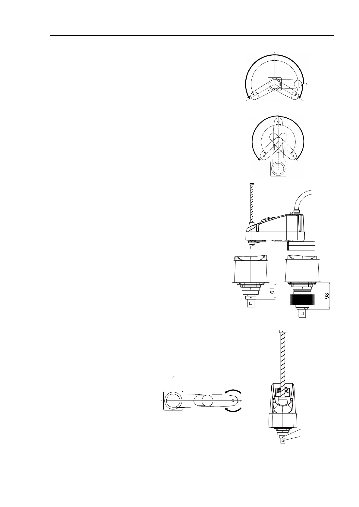
0 pulse position of Joint #1:
position aligned with X-axis in
Robot coordinate system
0 pulse
+
0 pulse position of Joint #2:
position where Arms #1 and #2
are in a straight line
(Regardless of the Joint #1
direction.)
0 pulse
+
0 pulse position of Joint #3:
upper limit position in motion
range
The height of Joint #3 depends
on manipulator model.
Standard model
Cleranroom model
0 pulse position of Joint #4:
position where the flat surface on the shaft (or
set screws of the mechanical stop on the
bottom) faces toward the tip of Arm #2
Flat Surface
Set Screws
0 pulse
+

Table of Contents

Questions and Answers:

Question and Answer IconNeed help?

Do you have a question about the Epson LS20-B Series and is the answer not in the manual?

Epson LS20-B Series Specifications

General IconGeneral
BrandEpson
ModelLS20-B Series
CategoryRobotics
LanguageEnglish

Related product manuals