Setup & Operation 5. Motion Range
54 L
S20-B Rev.4
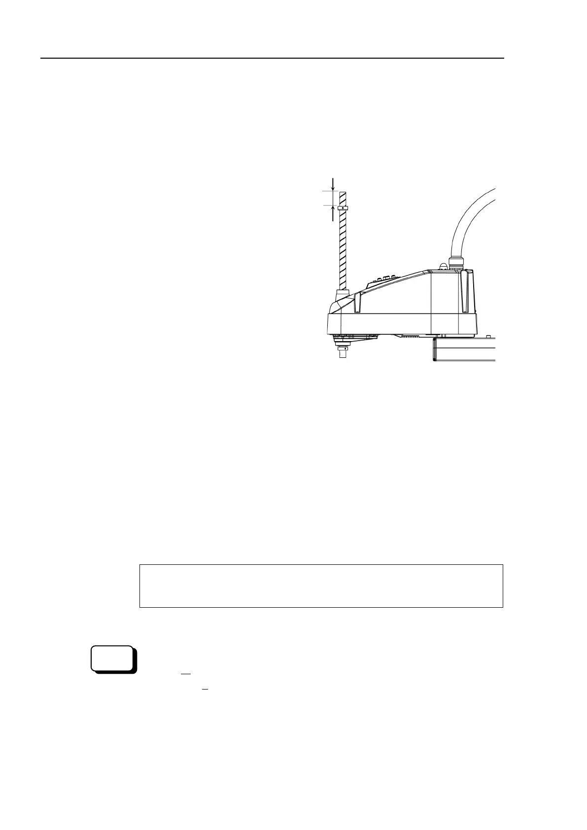
The upper end of the shaft
defines the maximum stroke. Move the lower limit
mechanical stop down by the length you want to limit the stroke.
For example, when the lower limit mechanical stop is set at
“420 mm” stroke, the
limit Z coordinate value is “−420”. To change the value to “−100”, move the
lower limit mechanical stop down
“320 mm”. Use calipers to measure the distance
adjusting the mechanical stop.
Firmly tighten the lower limit mechanical stop screw
(set screws: 2-M5×6).
Recommended tightening torque:
3.9 N·m (39.8 kgf·cm)
Controller.
Joint #3 to its lower limit while pressing the brake release switch, and
limit position. Do not lower the mechanical stop too far
may not reach a target position.
Calculate the lower limit pulse
value of the pulse range using the formula
shown below
and set the value.
T
he result of the calculation is always negative because t
he lower limit Z coordinate
value
is negative.
Lower limit of pulse (p
ulse)
= lower limit Z coordinate value (mm) / Resolution (
mm/pulse)
** For the Joint #3 resolution,
refer to the section Setup & Operation 2.4 Specifications.
Execute the following command from the [Command Window].
value in X.
>JRANGE 3,X,0 ' Sets the pulse range of Joint #3
(10)
Pulse command (Go Pulse command), move
Joint #3 to the lower limit
position of the pulse range at low speed.
If the mechanical stop range is less
than the
pulse range, Joint #3
will hit the mechanical stop and an error will occur.
When the
error occurs, either change
the pulse range to a lower setting
or extend the position of the
mechanical stop within the limit.

 Loading...


