Maintenance 7. Arm #3
LS20 Rev.4 105
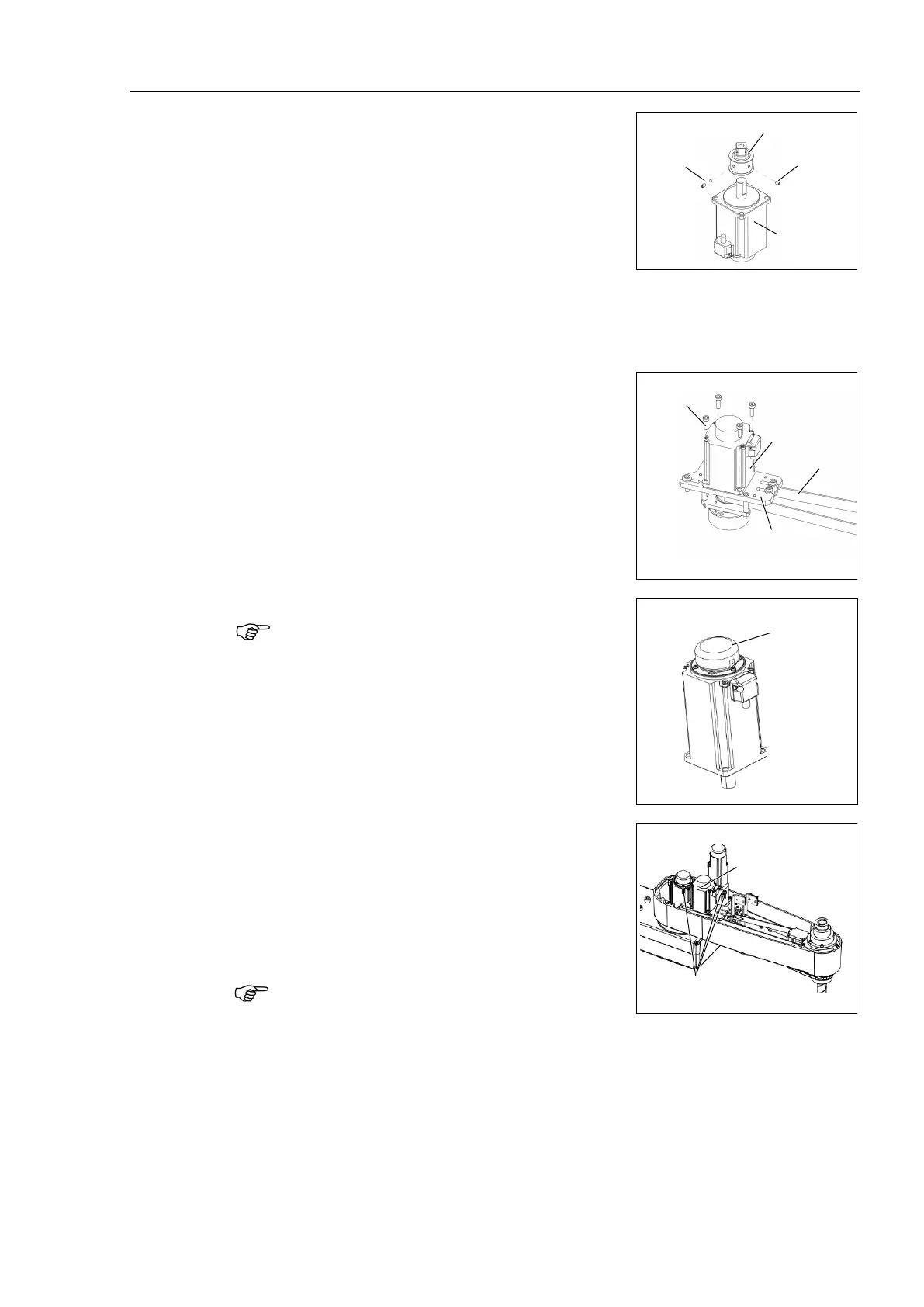
Joint #3 motor
Installation
the pulley to the Joint #3 motor.
the pulley where the pulley end face
the motor shaft end face.
M4×4
Set screw
+M4 Bushing
screws vertically on the flat
Insert a bushing into the other set
screw hole to
prevent damage to the motor shaft.
2)
to the motor plate while
aligning the hub to the brake disc
.
, set the motor so that the
inside of the Z belt.
When replacing the motor of
the Joint #3, remove
the cap from the old motor and install it to the new
one.
If the Manipulator is operated while the cap is not
installed, the motor may be
damaged due to
entering of the foreign materials into the rotating
part of
the motor sensor and interference of the
rotating part and the cables.
3)
Loosely secure the Joint #3 motor unit to Arm
#2.
that the teeth of the timing belt are
those of the pulley.
the motor unit can be moved by hand,
and it will not tilt when pulled.
f the unit is secured too loose or too
tight, the belt will not have the proper tension.
3-M5×20+washer for
slotted hole

 Loading...


