Maintenance 7. Arm #3
LS20 Rev.4 113
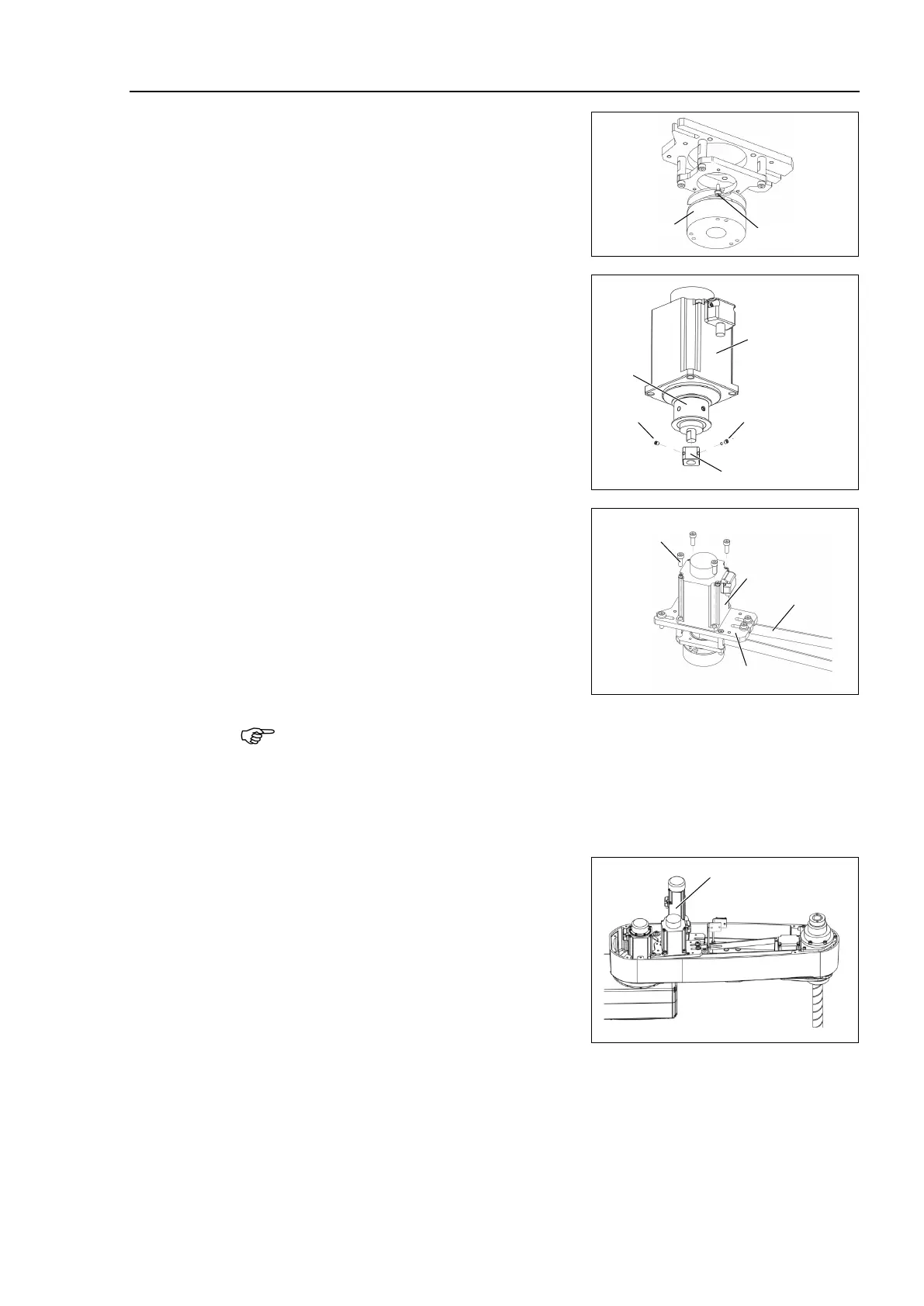
Joint #3 brake
Installation
Mount the brake to the brake plate.
ke hub to the pulley of the
unit.
ix the brake hub while aligning it to the
face of the pulley.
screws vertically on
face of the motor shaft.
Insert a bushing into the other set
screw
hole to prevent damage to the motor shaft.
M3×4 Set Screw
+M3 Bushing
motor to the motor
plate while aligning the hub to the brake
disc.
Before aligning the hub, set the motor so
that the pulley will be inside of the Z belt.
When the brake disc is not aligned, manually adjust the position
by following the
1. Connect the connector X32.
2. Press the brake release switch to release the brake.
3. Adjust the brake disk manually so that the hole is at the center.
Apply the proper tension to the Z belt, and
secure the Joint #3 motor
unit.
For details, refer to Maintenance 7.2
Replacing the Timing Belt.
Connect the following connector.
Connector: X32
the Arm Top Cover.
For details, refer to Maintenance: 3.1 Arm Top Cover.
Execute the calibration of Joint #3.
For details, refer to Maintenance: 13. Calibration.

 Loading...


