Set the O-ring removed in the removal
step (6) into the O-ring groove of the
Arm #1 and install the flexspline on the
Arm #1.
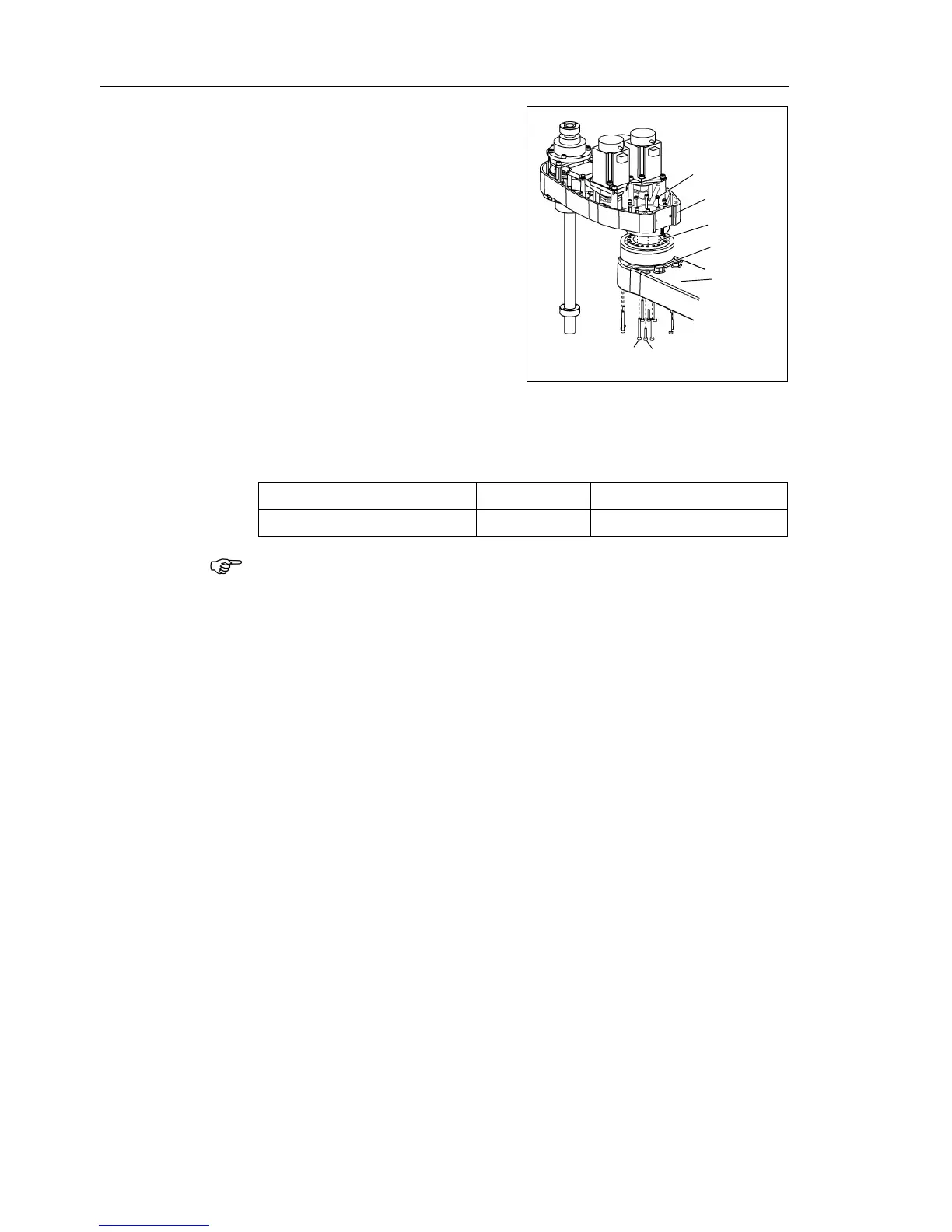
A: LS3: 10-M3×18
LS6: 16-M3×28
B: LS3: 8-M3×30+8-M3 small washer
LS6: 8-M3×32+8-M3 small washer
C: LS3: 4-M3×15+4-M3 small washer
LS6: 4-M3×12+4-M3 small washer
Loosely secure all bolts in a crisscross
pattern so that the bolts will be secured
evenly. Then, using a torque wrench,
tighten each bolt securely in a crisscross
pattern at the torque specified in the
table below.
Set the attached O-ring into the O-ring groove of the circular spline.
Secure the Arm #2 on the circular spline.

 Loading...


