Setup & Operation 1. Safety
12 LS Rev.10
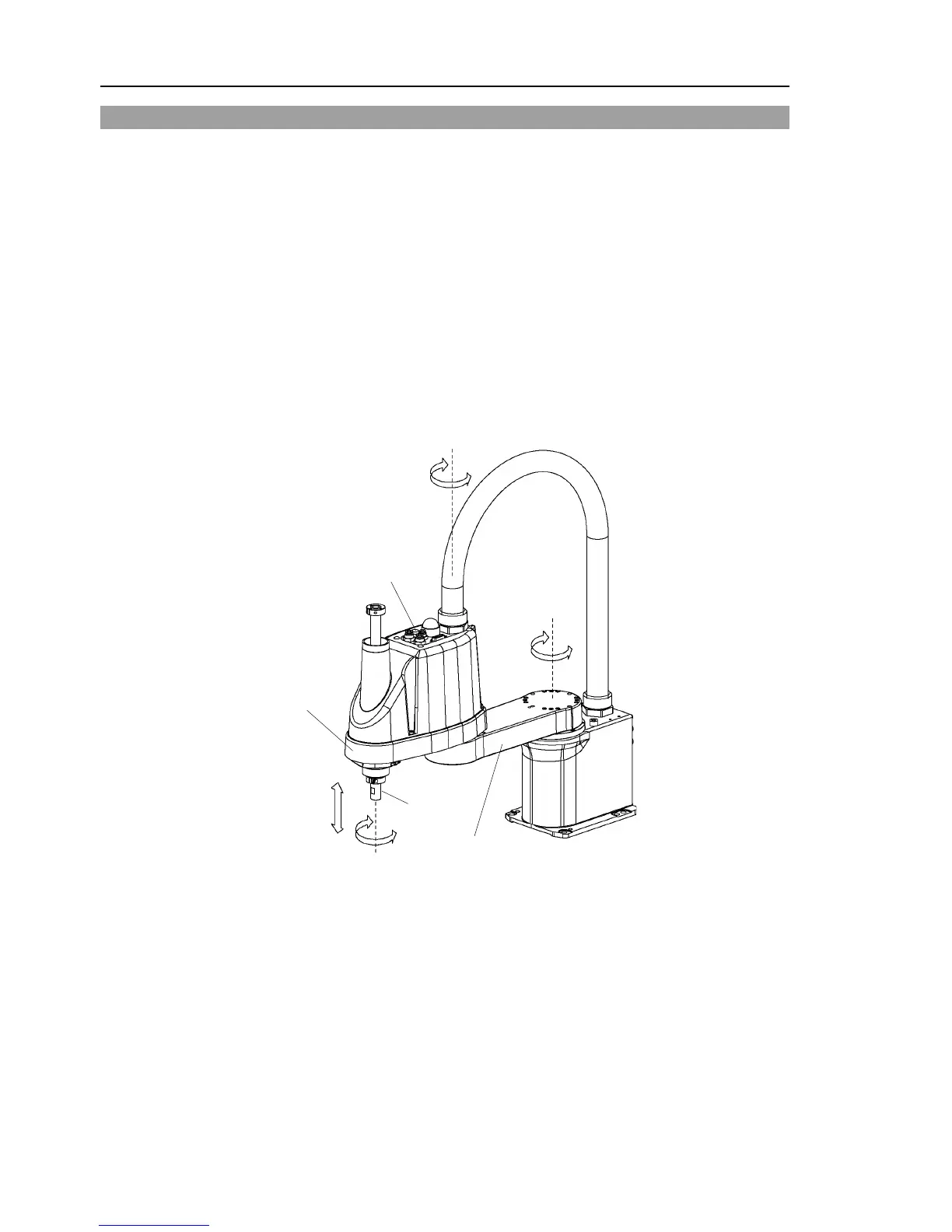
1.5 Emergency Movement Without Drive Power
When the system is placed in emergency mode, push the arm or joint of the Manipulator
by hand as shown below:
Arm #1 Push the arm by hand.
Arm #2 Push the arm by hand.
Joint #3 The joint cannot be moved up/down by hand until the solenoid
brake applied to the joint has been released. Move the joint
up/down while pressing the brake release switch.
Joint #4 LS3: Rotate the shaft by hand.
LS6: The shaft cannot be rotated by hand until the solenoid brake
applied to the shaft has been released. Move the shaft
while pressing the brake release switch.
LS3: The brake release switch affects only Joint #3. When the brake release switch is
pressed in emergency mode, the brake for Joint #3 is released.
Be careful of the shaft while the brake release switch is pressed because the shaft may
be lowered by the weight of an end effector.
LS6: The brake release switch affects both Joints #3 and #4. When the brake release
switch is pressed in emergency mode, the brake for both Joints #3 and #4 are released
simultaneously.
Be careful of the shaft falling and rotating while the brake release switch is pressed
because the shaft may be lowered by the weight of an end effector.

 Loading...


